
Fire resistant cable

Active Publication Date: 2006-08-10
RSCC WIRE & CABLE LLC
View PDF13 Cites 28 Cited by
  • Summary
  • Abstract
  • Description
  • Claims
  • Application Information

AI Technical Summary

Benefits of technology

[0010] In another aspect, the invention features a method for using a fire resistant cable. The method includes the steps of: connecting the cable to a power source, wherein the cable includes: a conductor, an inorganic braid substantially applied over the conductor, and a ceramifiable polymer substantially applied over the bra

Problems solved by technology

Presently, most electrical wires are at risk in a fire-related emergency.
Most wiring is not designed to sustain operation at high temperatures experienced in a fire.
Even more wiring is ill prepared to sustain operation in a fast-rising temperature environment, such as environments where the temperature increases by hundreds of degrees each minute.
During a fire-related emergency, this wiring is prone to failure.
However, this same wiring will typically fail within ten minutes in a fast-rising temperature scenario, even if that temperature never rises above 2000 degrees Fahrenheit.
Most wiring is not designed to survive a fast-rising temperature environment.
Cables that may pass these test tests will typically fail within 10 minutes in the UL 1709 test method.
The solid conductor, as well as the mineral insulation, and metal tube make MI cable difficult to handle.
This MI cable is not available in long lengths, and has a very high electrical resistance due to the nickel conductor.
This increased resistance requires an increase in conductor size, which limits lengths further, and makes the MI cable costlier and even harder to handle.
The solid conductor is susceptible to breakage due to fatigue of the metal when it is repeatedly bent as is required for value maintenance.
Finally, MI cable is susceptible to failure during exposure to moisture or water and any susceptibility to failure is undesirable in emergency power cables.
Thus, a heretofore unaddressed need exists in the industry to address the aforementioned deficiencies and inadequacies.

Method used


Image

  • Fire resistant cable
  • Fire resistant cable
  • Fire resistant cable

Examples


Embodiment Construction

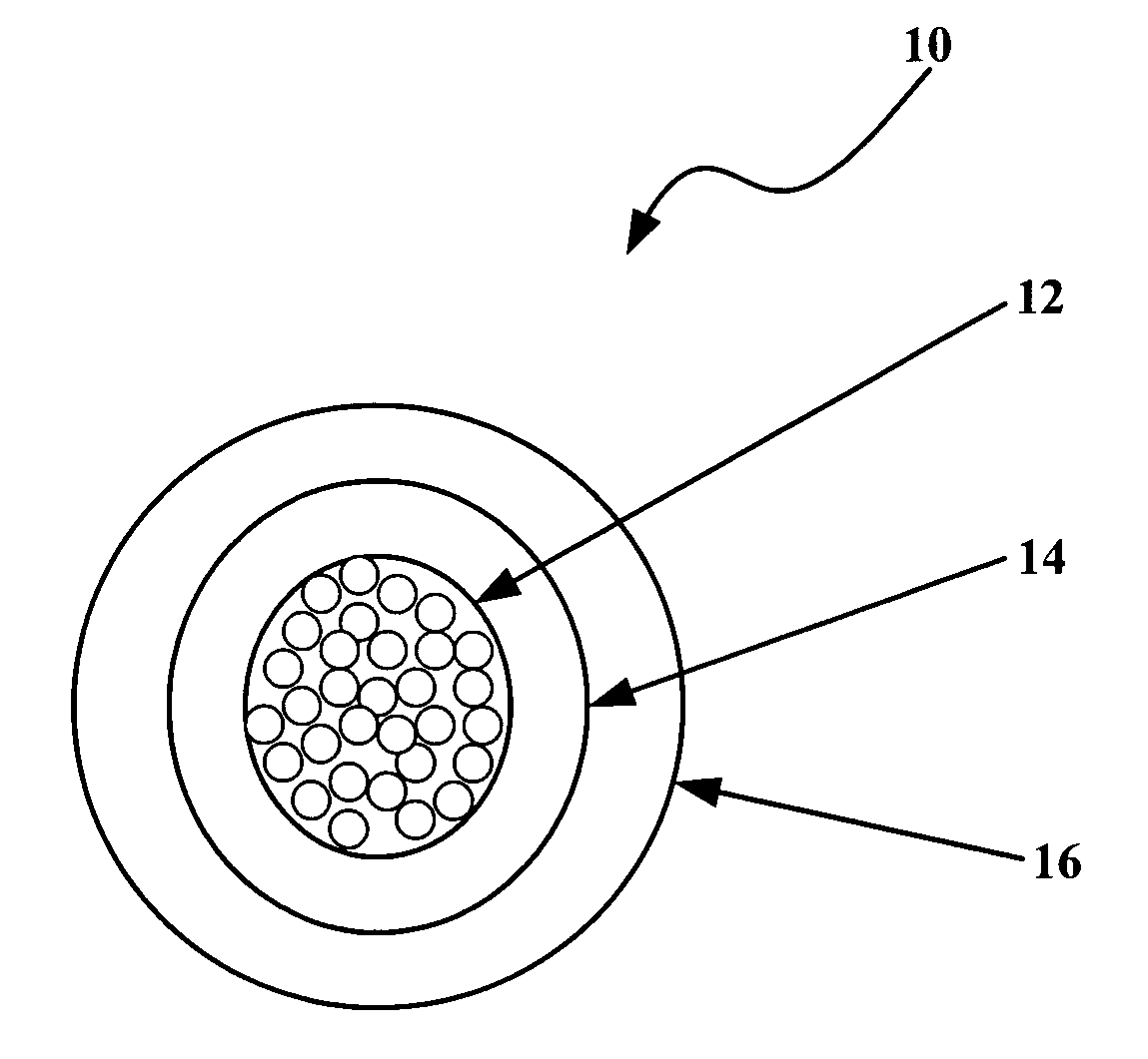
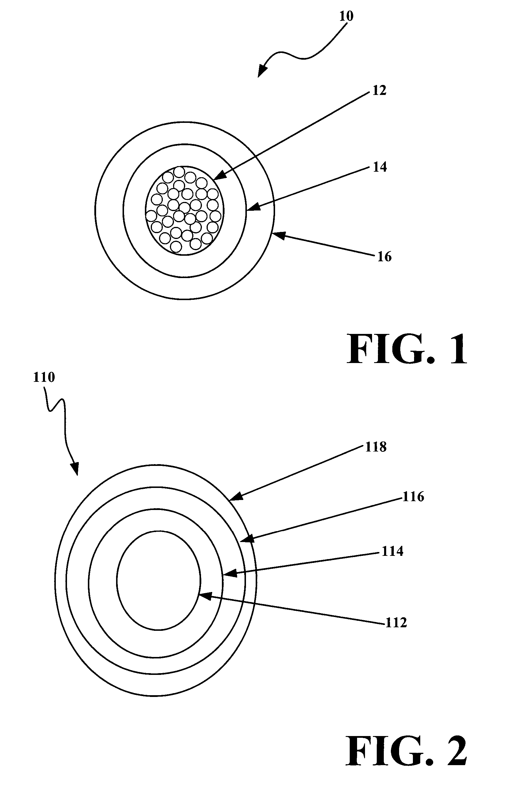
[0018]FIG. 1 is a cross-sectional drawing of a fire resistant electrical cable 10, according to a first exemplary embodiment of the invention. The fire resistant electrical cable 10 includes a conductor 12. Substantially applied around the conductor 12 is an inorganic braid 14. A ceramifiable polymer 16 is substantially applied over the braid 14.

[0019] The conductor 12 can be constructed in a variety of ways. The conductor 12 may be a single solid wire or it may be multiple wires bundled together. As is known to those having ordinary skill in the art, multiple stranded wires bundled together are easier to twist than a single, solid wire. The conductor 12 may include one or more nickel-coated copper wires. The conductor 12 may, as an example, include a 27% nickel conductor with oxygen-free high-conductivity copper, or it may be solid copper, solid nickel, or another similar conductive material. The preferred characteristics of the conductor 12 are that it is electrically conductive ...


PUM

PropertyMeasurementUnit
Temperatureaaaaaaaaaa

Abstract

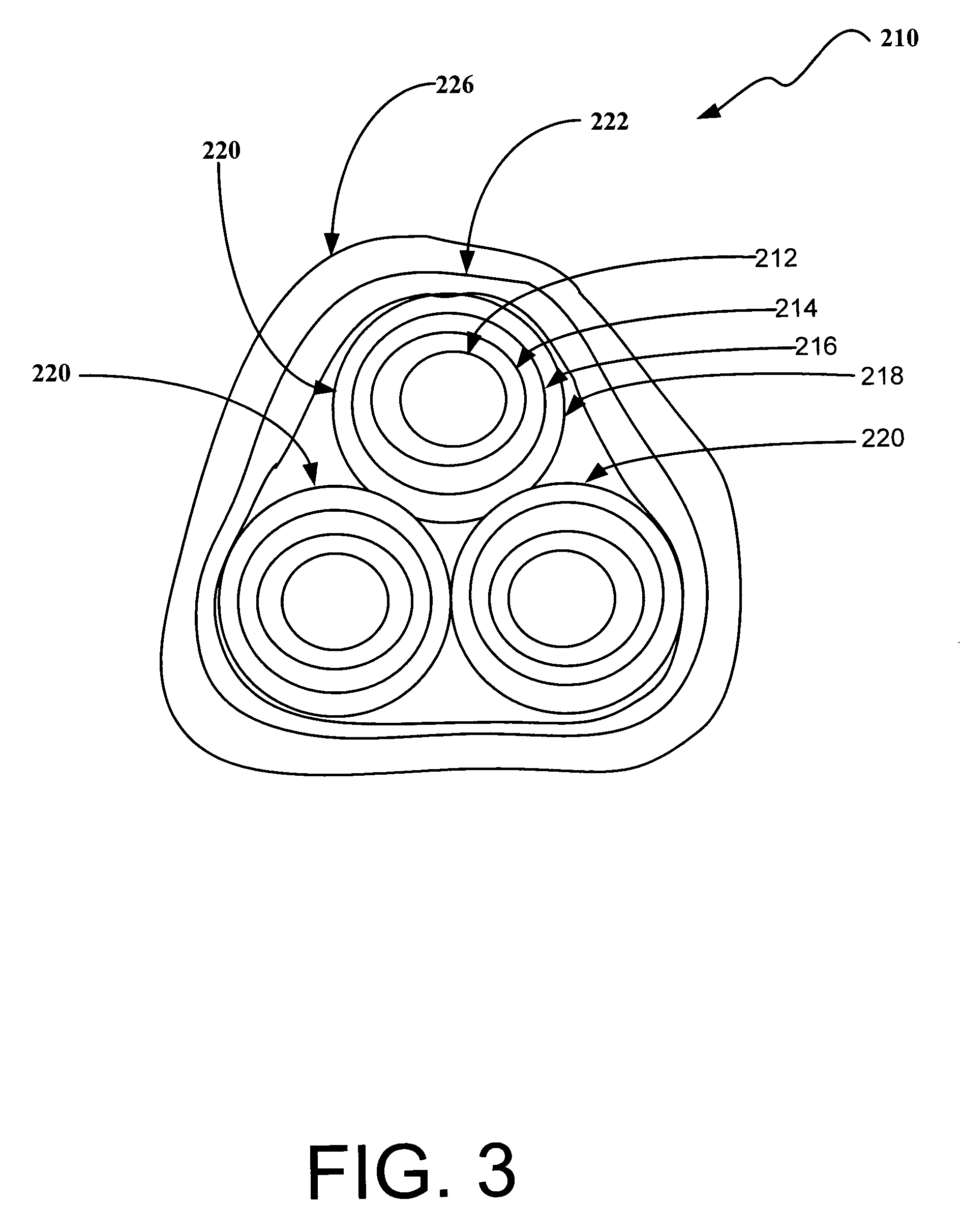
A fire resistant electrical cable includes a conductor. Substantially applied around the conductor is an inorganic braid. A ceramifiable polymer is substantially applied over the jacket. The fire resistant electrical cable also includes a retaining jacket substantially applied over the ceramifiable polymer. Multiple fire resistant electrical cables may be combined within a single grouping jacket to provide multi-phase conductance.

Description

FIELD OF THE INVENTION [0001] The present invention is in the field of electrical cable. More specifically, the present invention is in the field of fire resistant electrical cable. BACKGROUND OF THE INVENTION [0002] The availability of electrical devices during fires can have lifesaving implications. Exit signs and emergency lights guide where to go in an emergency. Hard-wired fire alarms alert people to an emergency situation. In hospitals and nursing homes, electricity is needed to power devices that are directly in use to sustain life. For a petroleum or chemical plant, operations of emergency electrically operated shutoff valves in a fire are critical to allowing safe shutdown of a plant before a fire can have catastrophic effects. [0003] Presently, most electrical wires are at risk in a fire-related emergency. Most wiring is not designed to sustain operation at high temperatures experienced in a fire. Even more wiring is ill prepared to sustain operation in a fast-rising tempe...

Claims


Application Information

Patent Timeline
IPC IPC(8): H01B3/44
CPCH01B3/46H01B7/295
Inventor KONNIK, ROBERTMENNONE, MICHAEL
Owner RSCC WIRE & CABLE LLC
Learn More