Tilt mechanism

a technology of tilt mechanism and pivoting plate, which is applied in the direction of machine supports, building scaffolds, domestic objects, etc., can solve the problems of time-consuming and laborious adjustment of prior art arrangements, and achieve the effect of being easily integrated into the devi

Inactive Publication Date: 2006-08-10
BANG & OLUFSEN
View PDF6 Cites 3 Cited by
  • Summary
  • Abstract
  • Description
  • Claims
  • Application Information

AI Technical Summary

Benefits of technology

[0014] It is a further objective of the invention to provide a system or mechanism which may be designed in a compact manner and which may readily be integrated in the device, e.g. the display panel and / or its support.

Problems solved by technology

However, these prior art arrangements are often very complicated and suffer from a number of drawbacks.
Thus, it should be understood that in order to adjust the tilt angle from e.g. a relatively large downwards tilt to e.g. a relatively large upwards tilt, the user will have to turn the pinion knob a large number of revolutions, which makes such adjustments time-consuming.
Further, this prior art mechanism suffers from the drawback that the display panel is not suspended in a balanced arrangement as the display panel is rotated in relation to the rod placed behind the panel.
This prior art system is relatively large and complicated as it comprises a first bracket for mounting to a wall, a second bracket for mounting the display panel, a pair of minor arms, a pair of major arms and connecting arms.
The screen is secured by a hinge to a base for tilting from a vertical position, in which it is substantially balanced, through positions of progressively increased tilt, in which the weight of the tube and associated parts becomes progressively displaced and the screen becomes more unbalanced.
Therefore, these systems are sensitive to variations in load, e.g. the weight of a display panel, and they may thus only be used in connection with a display having a specific weight or they may require adjustment when being used in connection with a display panel having a weight outside a predetermined weight range.

Method used


Image

  • Tilt mechanism
  • Tilt mechanism
  • Tilt mechanism

Examples


first embodiment

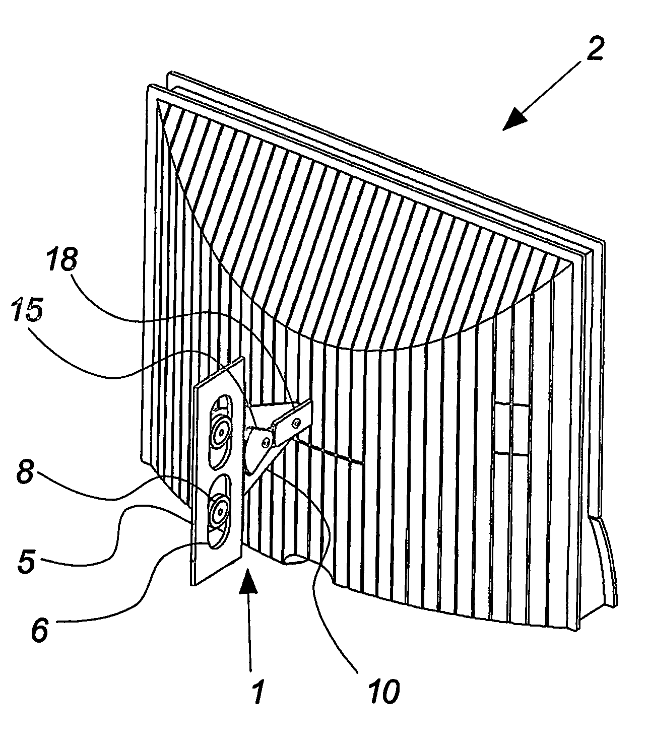
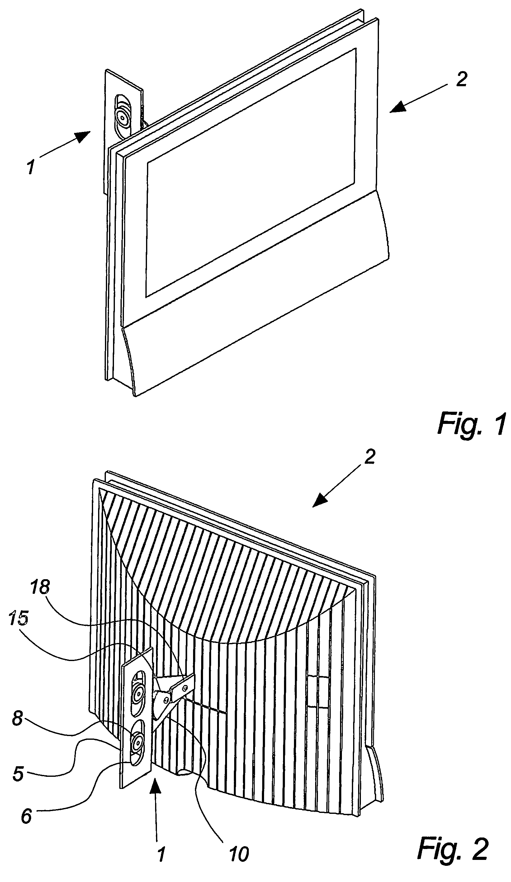
[0081] A mechanism according to the invention is illustrated in FIG. 1. The mechanism is generally designated 1 and is connected to a display screen or a display panel generally designated 2. This display screen may be a computer screen, a television screen or the like. Further, the screen or panel may be a cathode ray tube screen or a flat screen terminal such as a liquid crystal display (LCD), a plasma display panel (PDP) or the like. However, it should be understood that the mechanism according to the invention may be utilized in other applications, e.g. in connection with numerous other devices and items, in connection with which it is desirable to be able to perform an adjustment of an angle between two elements, e.g. support to an item such as an apparatus and the item itself.

[0082]FIG. 2 corresponds to FIG. 1, but FIG. 2 shows the mechanism from the rear. The mechanism 1 is shown schematically and it should be understood that the elements comprised in the mechanism may be des...

second embodiment

[0120] In the following, a second embodiment according to the invention will be described with reference to FIGS. 6-13.

[0121] This embodiment essentially corresponds to the first embodiment described above. The mechanism has, however, been encased in a support casing and a number of modifications has been introduced.

[0122] It is illustrated in FIGS. 6 and 7 that the tilt mechanism comprises a support member 18 with two support arms in the shown example. This support member 18 is connected to a support plate or bracket 40 which carries the display panel or screen 2. At the other end, the support member 18 is connected to a mechanism situated in a support casing 42. As shown, this support casing may be in the form of a cylindrical device which is connected to a support base 44. As shown, the support base 44 may be designed as a wall mount, e.g. by fixing to a wall or a similar element, with screws or the like through fixing holes 36. It should be understood that the support base may ...

third embodiment

[0132] the invention is illustrated in FIGS. 14 to 17 and shows a tilt mechanism generally designated 100 in connection with a table stand, although it should be understood that this embodiment relate to any form of stand or support for a display panel or another device, e.g. a floor stand, a wall support etc.

[0133] As shown in FIG. 14, a display panel 2 may be connected to a support member 118 carried by a support structure casing 102. As shown, this element 102 may be placed on a base part 101, in the form of e.g. a footplate. The support structure casing 102 may comprise one or more apertures, openings, slits etc. such as 103 and 104, which may serve to lead cables, wires etc., such as antenna cables, power cables, signal wires etc., from / to the interior of the casing 102 and to / from the display panel 2.

[0134] The mechanism according to this embodiment is illustrated schematically in FIG. 15, which illustrates a pivotally supported item 30 connected to a member 118. This member ...


PUM


Abstract

“Tilt mechanism for a device including a support member for supporting the device, a movable support member and a support structure. The support member is supported by the movable support member and the movable support member is supported by the support structure. The mechanism is further arranged to support the device essentially in a lateral direction of the movable support member, and the device may be supported by the mechanism in a state of equilibrium.”

Description

FIELD OF THE INVENTION [0001] The invention relates to a tilt mechanism as specified in claim 1, a display device comprising a display panel, for example a television screen, a computer screen or an information screen as specified in claim 26, and use of the tilt mechanism as specified in claim 28. BACKGROUND OF THE INVENTION [0002] Support arrangements for display devices are designed in numerous variations and some of these provide the possibility of adjusting the position of the display, e.g. for tilting, swiveling etc. of the screen. However, these prior art arrangements are often very complicated and suffer from a number of drawbacks. [0003] An example of such an arrangement is disclosed in U.S. Pat. No. 5,715,138 A. This document relates to an apparatus providing a display with tilting and rotating movements. This apparatus comprises a first housing placed behind the display panel and a second housing placed beneath the panel and the first housing. The first housing contains a...

Claims


Application Information

Patent Timeline
Patent Type & Authority Applications(United States)
IPC IPC(8): A47G29/00A47F5/12F16M11/10F16M13/02
CPCF16M11/10F16M11/18F16M13/02Y10S248/923
Inventor FRYDKJAER, JOHN
Owner BANG & OLUFSEN
Why Eureka
Try Eureka