Discharge lamp lighting device

a technology of discharge lamp and lighting device, which is applied in the direction of light source, electrical apparatus, instruments, etc., can solve the problems of deteriorating image quality of projectors, shortening the service life of hid lamps, and needing to reduce the brightness of hid lamps quickly, so as to achieve rapid modulation

Active Publication Date: 2006-08-10
USHIO DENKI KK
View PDF2 Cites 15 Cited by
  • Summary
  • Abstract
  • Description
  • Claims
  • Application Information

AI Technical Summary

Benefits of technology

[0022] As described above, the discharge lamp lighting device according to the present invention is capable of rapid modulation in which a lamp current of the lamp current rapidly is interrupted or reduced and restored rapidly.

Problems solved by technology

However, in certain instances, the brightness of the HID lamp needs to be reduced rapidly, or a current flowing through the HID lamp needs to be broken for a short time.
If the lamp current is slowly broken, it slowly returns to its original state, or overshoot or oscillation occurs in the waveforms of the lamp current at the time of return, the image quality of a projector is deteriorated.
In order to prevent the deterioration of image quality, the lamp current needs to return to its original state earlier than a required return timing for removing oscillation, which makes it difficult to reduce power consumption.
Therefore, even if the power supply circuit has capability of rapidly breaking the lamp current or of returning it to the original state, a long breaking time causes a problem in that the discharge lamp cannot resume discharge, or an abnormal emission spectrum occurs immediately after the discharge.
In this case, when the reduced lamp current is non-uniform due to a variation in the lamp current or a variation in characteristics depending on the life span of the lamp, the lamp current after returning from the reduced state to its original state is also non-uniform.
Then, the timing of resuming the spatial modulation of the projector apparatus is delayed, which causes a problem in that the waveform of the lamp current oscillates at the time of return.
Therefore, when the lamp power is modulated to change the brightness of the lamp, it is difficult to specify power only by specifying the lamp current.
However, the conventional techniques have the following problems.
As a first problem, it is difficult to rapidly modulate the brightness of a light source.
For example, in order for a high-speed modulation, the method needs to have a high-speed AD converter, a microprocessor, or a high-speed analog divider or multiplier, which results in an increase in manufacturing costs.
In this method, since the signal processing is performed every sampling period, it is difficult for an illumination request generating circuit to control modulation timing.
In a method in which a timing signal is provided to give processing timing, since the time until the microprocessor responds to the timing signal by interruption depends on the processes that has been performed inside the processor until that time, the modulation timing cannot be accurately defined.
According to this method, it is unnecessary to change the power target value with time, resulting in a high-speed operation.
However, this method has problems in that it cannot appropriately cope with a variation of the lamp voltage or a variation thereof with time, and be applied to deep modulation including the breaking of the lamp current, which is required for the above-mentioned breaking and reduction modulation.
However, in case of deep modulation, a lamp voltage is excessively greatly changed due to modulation.

Method used


Image

  • Discharge lamp lighting device
  • Discharge lamp lighting device
  • Discharge lamp lighting device

Examples


Embodiment Construction

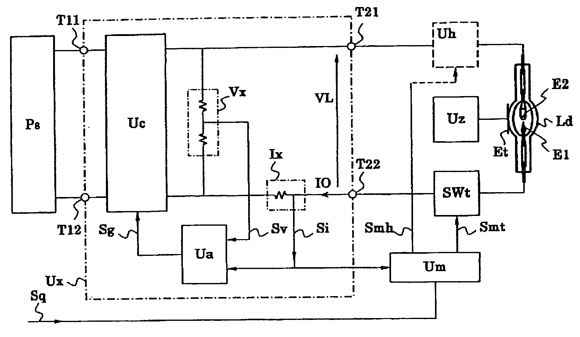
[0044]FIG. 1 is a block diagram schematically illustrating an embodiment of a discharge lamp lighting device according to the invention. An embodiment according to the invention will be described with reference to FIG. 1. The discharge lamp Ld is connected to a start circuit Uz for starting the discharge thereof. FIG. 1 shows an external trigger method in which a high voltage is applied to a trigger electrode Et provided at the outside of the discharge lamp Ld. However, the trigger method does not concern the essence according to the invention. A power supply circuit Ux is connected so as to supply power to the discharge lamp Ld through main discharge electrodes E1 and E2 of the discharge lamp Ld. The power supply circuit Ux has a function for converting the power supplied from a DC power source Ps into power suitable for the discharge lamp Ld by using a converter Uc of, for example, a down-chopper type or an up-chopper type.

[0045] An output current detecting unit Ix detects an out...


PUM


Abstract

The present discharge lamp lighting device is capable of rapid modulation in which a lamp current is rapidly reduced and rapidly restored. The current control circuit is provided to perform specific current control such that the brightness of a lamp is reduced by a predetermined percentage without being affected by a variation or change in lamp voltage over time, thereby reducing a lamp current.

Description

RELATED APPLICATION [0001] The disclosure of Japanese Patent Application No. 2005-032467, filed Feb. 9, 2005, including the specification, claims and drawings thereof, is incorporated herein by reference in its entirety. TECHNICAL FIELD OF THE INVENTION [0002] The present invention relates to a discharge lamp lighting device for lighting a discharge lamp, particularly, a high intensity discharge lamp, such as a high-pressure mercury lamp, a metal halide lamp, and a xenon lamp. DESCRIPTION OF RELATED ART [0003] For example, a high intensity discharge lamp (an HID lamp) is used for a light source device of an image displaying optical apparatus, such as a liquid crystal projector or a DLP™ projector. In order to light this type of lamp, a voltage, called a no-load open discharge voltage, is applied to the lamp, and then a high voltage is overlapped with the voltage to generate a dielectric breakdown in a discharge space. Then, a glow discharge and an arc discharge sequentially occur. [...

Claims


Application Information

Patent Timeline
Patent Type & Authority Applications(United States)
IPC IPC(8): H05B41/36
CPCH05B41/2925
Inventor OKAMOTO, MASASHISAMEJIMA, TAKANORI
Owner USHIO DENKI KK
Why Eureka
Try Eureka