Object detection system: zone matching and programmability

a technology of object detection and zone matching, applied in the field of vehicle object detection system, can solve the problems of large missed detection areas, mismatch between sensor coverage area and compatibility issue of many sensor technologies,

Active Publication Date: 2006-08-10
ARRIVER SOFTWARE LLC (N D GES D STAATES DELAWARE)
View PDF14 Cites 34 Cited by
  • Summary
  • Abstract
  • Description
  • Claims
  • Application Information

AI Technical Summary

Benefits of technology

[0009] In satisfying the above need, as well as overcoming the enumerated drawbacks and other limitations of the related art, the present invention provides an improved object detection system.

Problems solved by technology

This poses a compatibility issue for many sensor technologies.
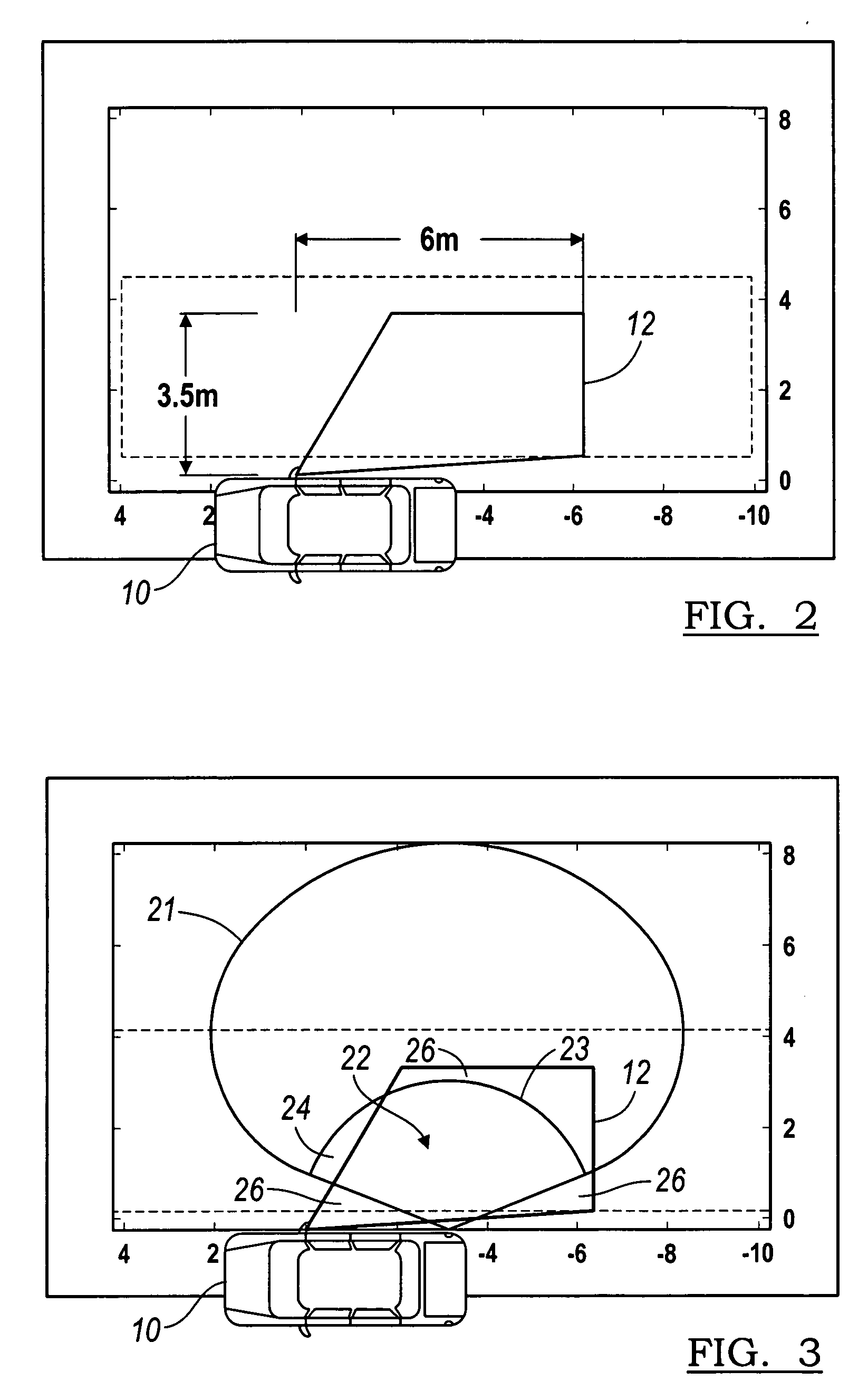
Typically, a mismatch exists between the sensors coverage area, which is commonly defined by the sensor's radiation pattern or optical field of view, and the desired detection zone.
The problem with this type of implementation is clearly evident, the mismatch between the sensor's sensing zone 21 and the desired side object detection zone 12 results in substantial missed detection areas 26 or false alarm areas 24.

Method used


Image

  • Object detection system: zone matching and programmability
  • Object detection system: zone matching and programmability
  • Object detection system: zone matching and programmability

Examples


Embodiment Construction

[0021] Referring now to FIG. 4, an object detection system embodying the principles of the present invention is illustrated therein and designated at 10. As its primary components, the object detection system 10 includes a controller 30 and an object sensor 32. The controller 30 is in electrical communication with the object sensor 32. The object sensor 32 may be a variety of range sensors including technologies such as radar, ultrasonic, infrared, or laser including monopulse technology. As such, the object sensor 32 may also determine an azimuth angle of object using, for example, monopulse technology. If the object sensor 32 determines the azimuth angle of the object, the azimuth angle is provided to the controller 30 by the object sensor 32.

[0022] Further, the controller 30 controls the object sensor 32 with regard to the sensor's sensing field 40 and range gate 42, as shown in FIG. 5. The sensing field 40 includes the angle and distance within which the sensor can detect an ob...


PUM


Abstract

The object detection system includes an object sensor and a controller. The controller is configured to compare a sensed range of an object with a range gate based on the azimuth angle of the object. The range gate for each azimuth angle is programmable and is selected to form a contiguous sensing region closely matching the shape of a desired detection zone. The object sensor is switchable between the plurality of sensing fields, wherein a range gate for each sensing field is programmable to form a contiguous sensing region. The object sensor may be a variety of range sensors including radar, ultrasonic, laser or infrared technologies. The range gate and parameters of the sensing field are each programmable through a controller. Further, the controller may automatically vary the range gate or sensing field based on vehicle parameters.

Description

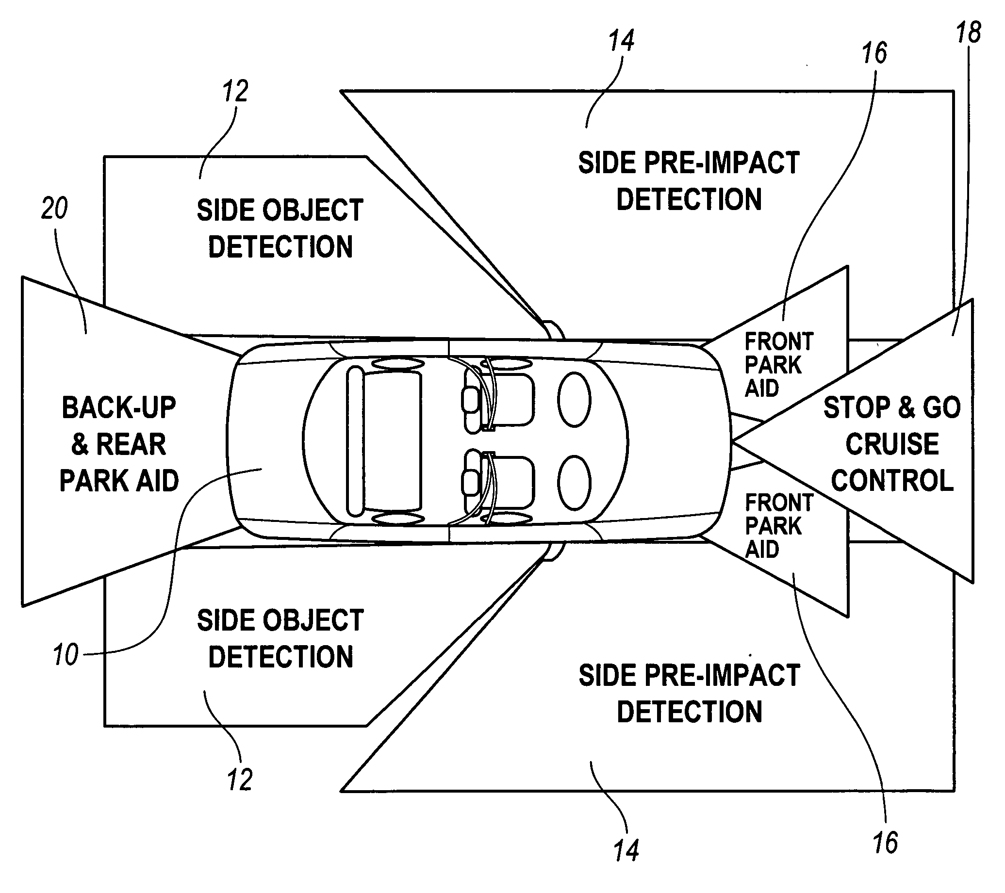
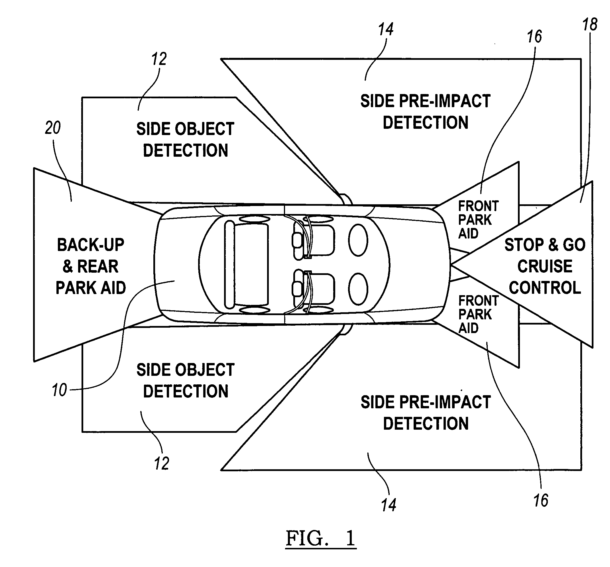
BACKGROUND [0001] 1. Field of the Invention [0002] The present invention generally relates to an object detection system for a vehicle. [0003] 2. Description of Related Art [0004] Automotive remote sensing systems are being developed to provide a variety of functional features involving the detection of objects in the near vicinity of the host vehicle. These remote sensing systems can be referred to as near obstacle detection systems (NODS). Individual NODS applications can provide various functional features such as side object detection, parking assistance, backup assistance, and pre-impact sensing. For these NODS applications, the sensing system is responsible for detecting and locating objects within a defined detection zone around the vehicle. The size and shape of the detection zone for which the sensing system must provide coverage varies with the functional features provided by the NODS application. For example, FIG. 1 shows the potential detection zones for various NODS app...

Claims


Application Information

Patent Timeline
Patent Type & Authority Applications(United States)
IPC IPC(8): B60Q1/00G01S13/00G08G5/04G01S13/931
CPCG01S13/18G01S13/42G01S13/931G01S2013/9353G01S2013/9357G08G1/16G01S2013/9332G01S2013/9321G08G1/168G01S2013/93274G01S2013/9315G01S2013/93272G01S2013/9322G01S2013/932G08G1/163
Inventor ZORATTI, PAUL K.ATTARD, JOE C.
Owner ARRIVER SOFTWARE LLC (N D GES D STAATES DELAWARE)
Why Eureka
Try Eureka