[0006] An inkjet printer according to the present invention may be used to easily determine the
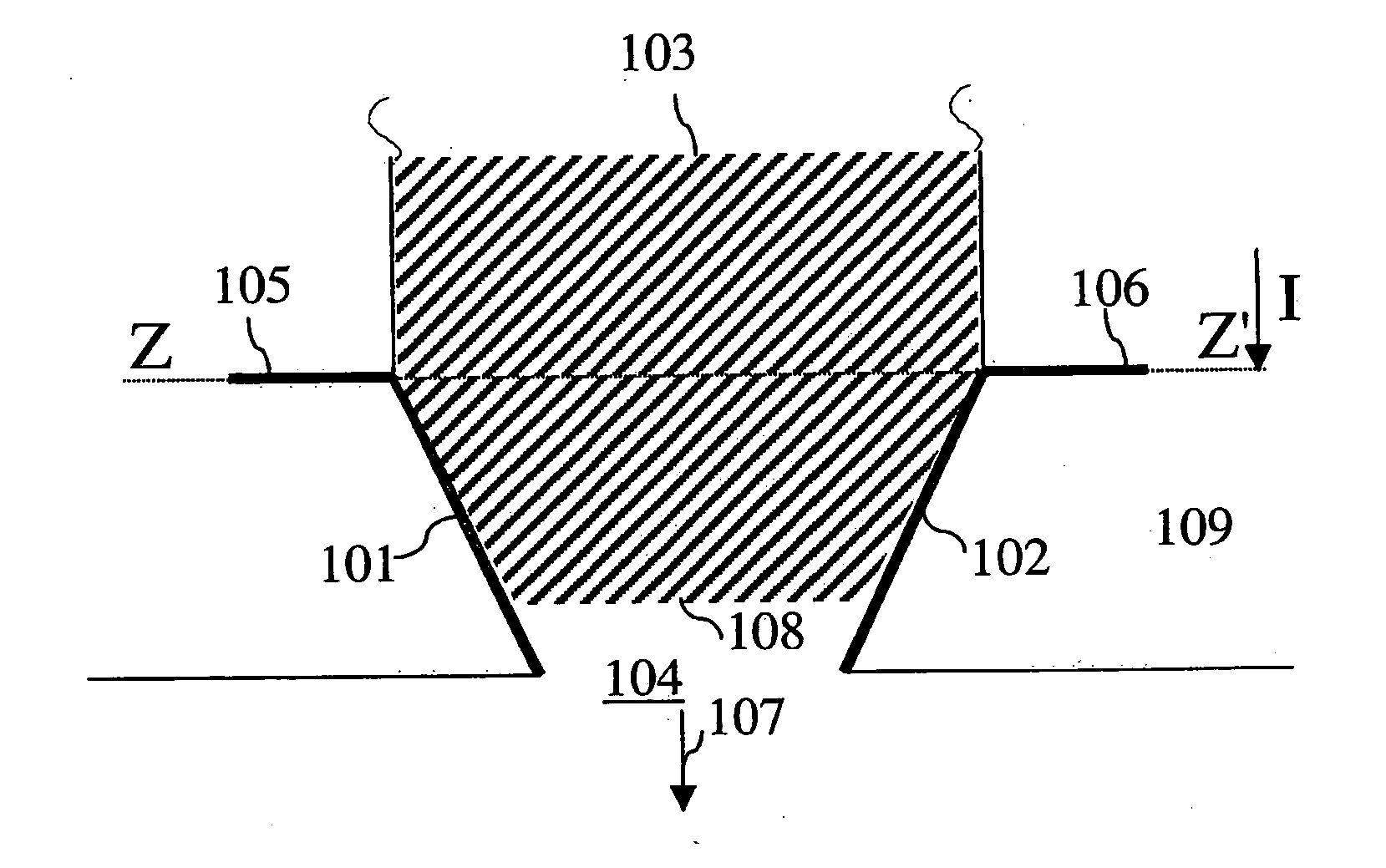
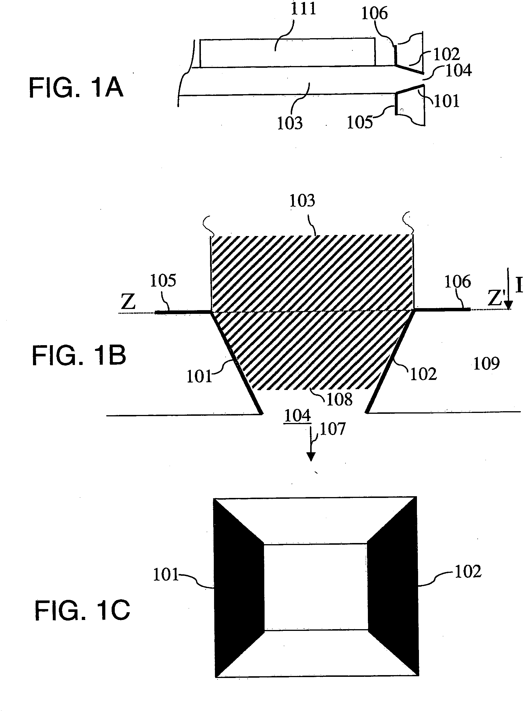
meniscus position of the ink in the vicinity of the exit opening by measuring the capacity. In the vicinity of the exit opening, the duct may be filled with air, ink or a mixture of air and ink. During operation, the
meniscus position will be between two electrically conducting parts. Ink has a different dielectrical constant compared to air, which is why, for example, the air between the two electrically conducting parts contribute, to a lesser extent, to the value of the capacitor capacity than the ink between the two electrically conducting parts. By applying a
voltage across the two electrically conducting parts, electrons will move (current). Here, the current produced depends on the value of the capacity and the applied
voltage. T he capacity may be measured so that the meniscus position may be determined. It will be understood by those skilled in the art that “an electrically conducting part fitted against a duct wall” may also mean, for example, that an electrically conducting part is integrated into a duct wall.
[0009] Another embodiment of the
present method comprises imposing an actuation pulse on an
actuator which is operationally connected to the duct so that an ink drop is ejected from the exit opening, and determining a variation of the meniscus position as a result of the actuation pulse. This method may be used to determine the meniscus position at various moments in time to be able to quickly and accurately determine a variation in the position. Thus, the variation of the meniscus position may be determined for the period when, for example, a drop is formed in the duct and the ink stabilises in the duct after the drop has formed. An
advantage is that the variation of the meniscus position may be used to, for example, determine whether the ink is sufficiently at rest to be able to eject an ink drop. If the ink has insufficiently reached a
rest state, it is possible, for example, to wait until this has been reached.
[0011] Another embodiment according to the present invention comprises modifying another actuation pulse based on the variation. In other words, the variation of the meniscus position is measured and, based on this data, the actuation pulse may be modified before the next ink drop, for example to achieve improved drop formation. The
advantage of this method compared to the previous embodiment is that this leaves more time to carry out complex calculations. If, for example, it appears at the start of the pulse that the meniscus position is increasing much too quickly in the direction of the exit opening, for whatever reason, the next pulse may be modified by adjusting it in its further course based on this information. Another example is that if the ink in the duct has insufficiently quickly reached a
rest state, the next pulse may actively influence the ink, so that it reaches a sufficient
rest state faster.
[0013] Another embodiment of the present invention comprises a feedforward controller known as ILC (
Iterative Learning Control) actuation technology. This control technology allows for optimum actuation pulses to be systematically generated with which preset objectives may be achieved. This method may be used to quickly and accurately determine the meniscus position at various moments in time, and thus also a variation of the position, for example for the period when a drop is formed in the duct and for the period when the ink stabilises in the duct after the drop has formed. ILC actuation technology compares the variation to a reference variation (a variation of the meniscus position that results in a specific objective being achieved) and modifies an actuation pulse so that the discrepancy between the actual variation and the reference variation is eliminated. ILC actuation technology is suitable for modifying repetitive similar tasks to a predetermined objective: to achieve higher jet frequencies, to eliminate cross-talk, to compensate for changed dynamics or to enable
drop size modulation. This ILC actuation technology has the extra
advantage that it is less calculation intensive compared to
feedback control technology.
[0014] By applying the method in an inkjet printer according to the present invention, it is possible to take the effects of printhead
ageing into account so that there is no more noticeable effect on the drop ejection. Any effect that
ageing has on the drop ejection process may be corrected by application of this method. For example, if wear of the printhead leads to a deviant variation of the meniscus position, then the actuation pulse may be modified so that the correct variation of the meniscus position is achieved. A deviant variation of the meniscus position could occur, such as for example, reduction of the expansion of the converter in response to a given pulse, wear of the exit opening, weakening of the flexible plate, cracks in the printhead, or loosening of connections, etc. The compensation of the effects of
ageing may be effected by updating each actuation pulse, or by measuring the effects of ageing at certain times, for example, during a service call, and modifying the actuation pulse to said measurement. The latter embodiment is easy to implement and is often sufficient if the printhead is not ageing quickly.
[0015] The jetting frequency may be made much higher using the method in an inkjet printer according to the present invention. By modifying the actuation pulse, the meniscus movement may be more quickly brought to rest at the desired meniscus position. For example, by forming the actuation pulse after the drop ejection in such a manner that it yields a
pressure wave opposed to the
pressure wave of the kind passing through the ducts, the damping may take place in a much shorter time so that the meniscus position is at rest in a short time and at the correct location. As a result, the next actuation pulse may be provided more quickly while maintaining good drop properties. It is also possible to let the next actuation pulse take place in any manner whatsoever, i.e., without a distinctly active damping, after a prior drop ejection and actively correct the variation of the meniscus position.
