
Brightness-enhancing integral polarizer and optical film structure and a manufacturing method thereof

a technology of integral polarizer and optical film, which is applied in the direction of optics, instruments, optical elements, etc., can solve the problems of affecting the brightness of the display, so as to achieve the effect of reducing the light transmittance, reducing the polarization and light transmittance level of different films, and poor matching of optical effects

Inactive Publication Date: 2006-08-10
TAIWAN TFT LCD ASSOC +7
View PDF17 Cites 12 Cited by
  • Summary
  • Abstract
  • Description
  • Claims
  • Application Information

AI Technical Summary

Benefits of technology

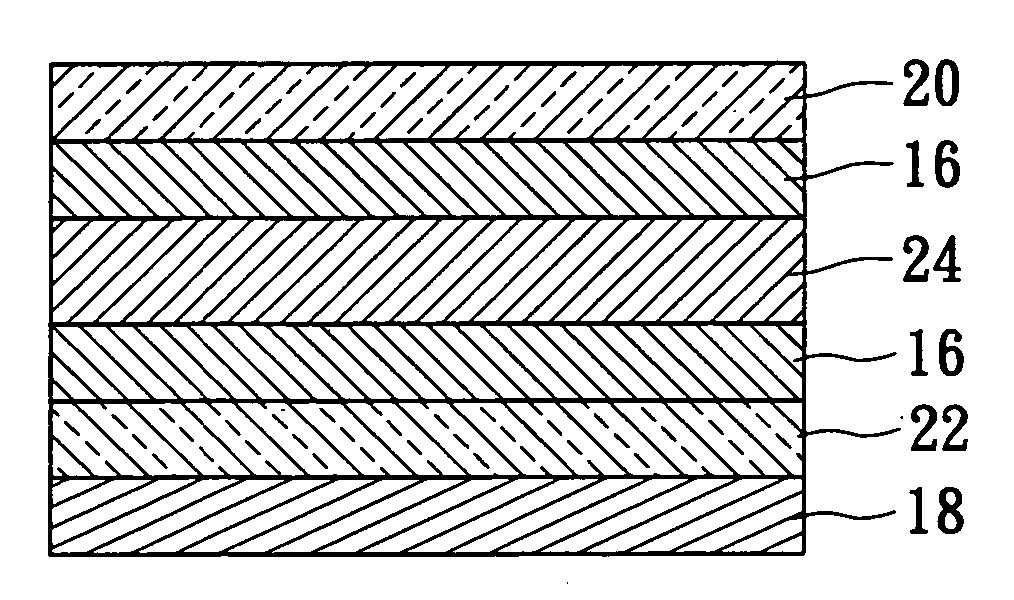
[0016] Therefore, it is a primary objective of the present invention to provide a brightness-enhancing integral polarizer and optical film structure, and a manufacturing method for the same, that primarily adopt a system assembly model to overcome the overall poor match of optical effect of the traditional polarizer and brightness-enhancing film, causing an overall decrease of the light transmittance and having its polarization contributed by the polarizer only. The present invention rearranges the polarization and light transmittance level of different films to produce an overall polarization and light transmittance level higher than those of the polarizer accompanied with the brightness-enhancing film. The invention also has the effect of a reflective light, and thus the brightness-enhancing integral polarizer together with the optical film in accordance with the present invention can fully obtain a light transmittance effect for the first and second times, without incurring an optical loss.

Problems solved by technology

The absorption and light transmission of a dichroic polarizer in a display are the main factors that affect brightness, and thus increasing the intensity of a light source and its light transmittance level is a main issue for displays.
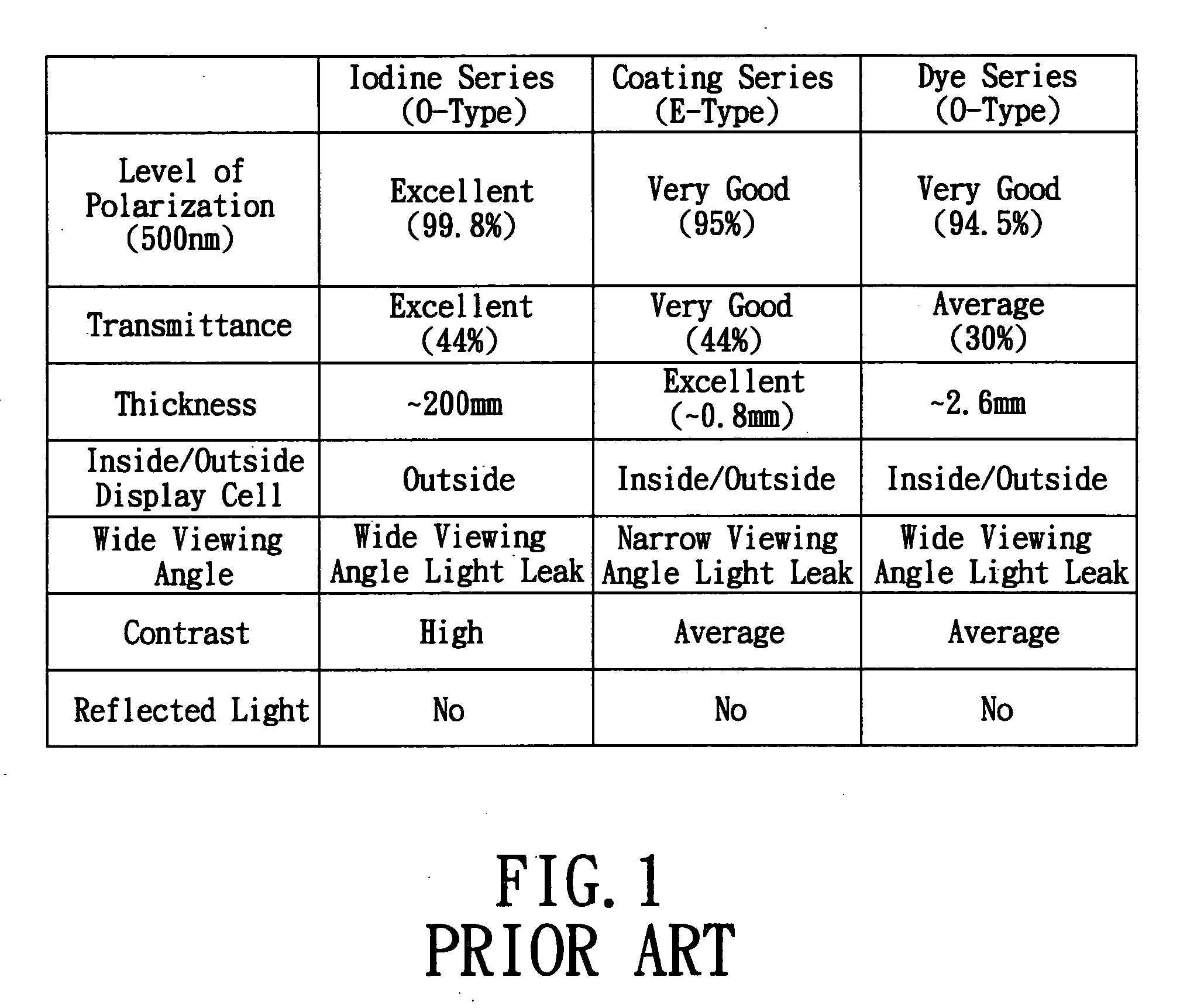
At present, the transmittance of the current iodine polarizers is up to 44% to 46%, and has approached a level that makes a further improvement of the light transmittance level difficult.
Its main advantages include (1) a high degree of polarization (99.9%); (2) a high light transmittance level (44%-46%), and its main disadvantages include (1) a large viewing angle that gives a strong leakage of light, thus requiring a wide viewing angle film to achieve a high contrast effect; (2) poor climate resistance; (3) low mechanical characteristic, thus requiring a protective film to enhance the mechanical characteristic thereof, and (4) a requirement of being used and attached on the exterior of the display.
The E-type polarizer has the disadvantages of (1) having insufficient polarization level and light transmittance level for the TFT-LCD and (2) having a small viewing angle that will cause a light leak.
The dye series polarizer has the disadvantages of (1) having difficulties of obtaining a dye with a high absorption level, (2) a high level of polarization requires a dye with a high concentration, and thus results in high costs, and (3) a thick film (approximately 3 μm) causes a decrease of light transmittance and thus limits the applications of the dye series polarizer.
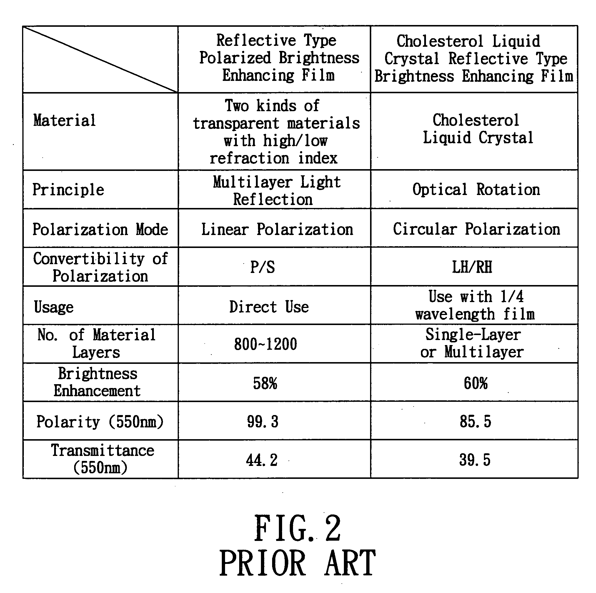
Therefore, the multilayer film does not have a good optical effect, but has a large loss of light transmittance level.
Even if a light-enhancing film is added, the whole light enhancement effect of the light-enhancing film cannot be shown.
If a cell is manufactured in the future, then a common light-enhancing film sold in the market usually comes with a thickness exceeding 100 mm (over 100 mm for the DBEF), and such thickness will cause a shift of drive voltage in the cell that makes the manufacture difficult.
After immersing a uniaxially stretched film of the PVA in an iodine solution to produce a light polarizer, qualities such as the mechanical characteristic, climate resistance, and heat resistance of the film layer are poor.

Method used


Image

  • Brightness-enhancing integral polarizer and optical film structure and a manufacturing method thereof
  • Brightness-enhancing integral polarizer and optical film structure and a manufacturing method thereof
  • Brightness-enhancing integral polarizer and optical film structure and a manufacturing method thereof

Examples


Embodiment Construction

[0026] The above and other objects, features, and advantages of the present invention will become apparent from the following detailed description taken with the accompanying drawings. However, the drawings are provided for reference and illustration, and are not intended to limit the present invention.

[0027] If light passes through two polarizers stacked with each other, the total thickness of the polarizers is greater than the thickness of a single polarizer, thus increasing the light transmitting thickness. Although such an arrangement increases absorbability and polarization, it suffers a significant loss of light transmission. In addition to the basic film problems, the two stacked polarizers also have an optic axis alignment problem. If the polarized light produced by a first polarizer enters a second polarizer, some portion of the light intensity is absorbed due to the deviation angle of the optic axis alignment. The light transmission level will thus drop. Although the two ...


PUM

PropertyMeasurementUnit
light transmittanceaaaaaaaaaa

Abstract

A brightness-enhancing integral polarizer and optical film structure and manufacture are described. The brightness-enhancing integral polarizer and optical film have an absorptive polarizer and a reflective polarizer. The reflective polarizer generates a reflective light source effect, and uses a nonlinear optic design to coat a brightness-enhancing integral polarizer and optical film with a different dye on at least one substrate and produce the effects of brightness enhancement, high polarization, high transmittance, wide viewing angle and high contrast for the brightness-enhancing integral polarizer and optical film structure and manufacturing method.

Description

BACKGROUND OF THE INVENTION [0001] 1. Field of the Invention [0002] The present invention relates to a brightness-enhancing integral polarizer and optical film structure and a manufacturing method for the same, and more particularly to a brightness-enhancing integral polarizer and optical film structure, and a manufacturing method for the same, that use a non-linear optical design to coat a brightness-enhancing integral polarizer and optical film with a different dye onto at least one substrate. The brightness-enhancing integral polarizer and optical film include two kinds of polarizers, an absorptive polarizer and a reflective polarizer, and the reflective polarizer provides a reflective light source and concurrently features enhanced reflective brightness, high degree of polarization, high transmittance, wide viewing angle and high contrast. [0003] 2. Description of Related Art [0004] A liquid crystal display mainly uses a linear polarization produced by two polarizers to achieve ...

Claims


Application Information

Patent Timeline
Patent Type & Authority Applications(United States)
IPC IPC(8): G02F1/1335
CPCG02B5/305
Inventor JENG, YUE-SHIHCHEN, YUH-SHYANGLIU, WEI-CHIHWANG, TSUNG-HSIUNGWU, YU-HSUNCHIEN, WEI-YI
Owner TAIWAN TFT LCD ASSOC
Learn More