
Optical disc device

a technology of optical discs and optical discs, applied in the field of optical disc identification techniques, can solve the problems of difficult to receive the influence of noise, and achieve the effects of reducing processing load, reducing noise, and improving operability

Inactive Publication Date: 2006-08-10
FUNAI ELECTRIC CO LTD
View PDF7 Cites 1 Cited by
  • Summary
  • Abstract
  • Description
  • Claims
  • Application Information

AI Technical Summary

Benefits of technology

[0011] The present invention has been made to solve the aforementioned problems, and it is an object of the present invention to provide an optical disc device capable of realizing a shorter identification time for an optical disc and achieving accurate disc identification with a smaller processing load.
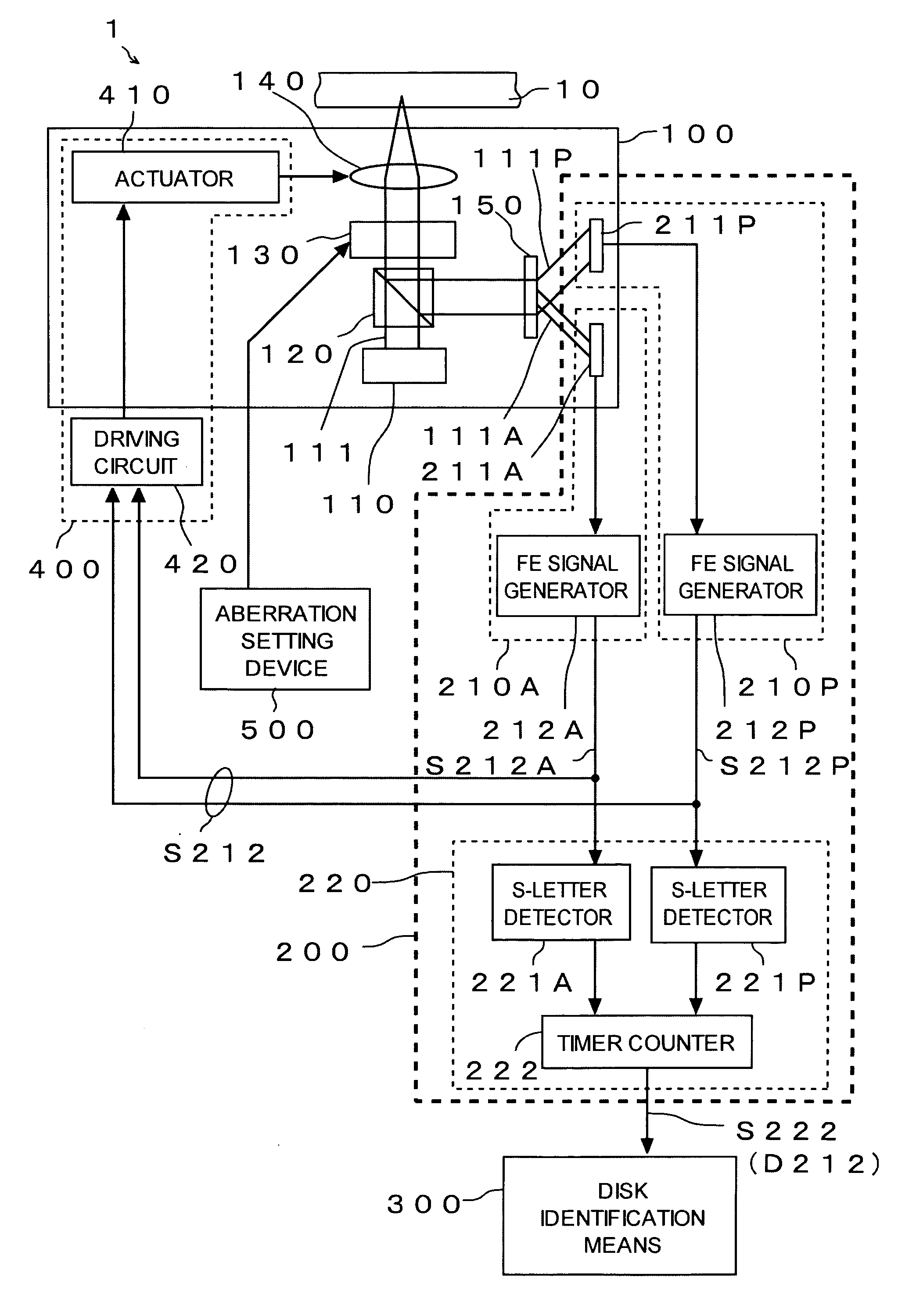
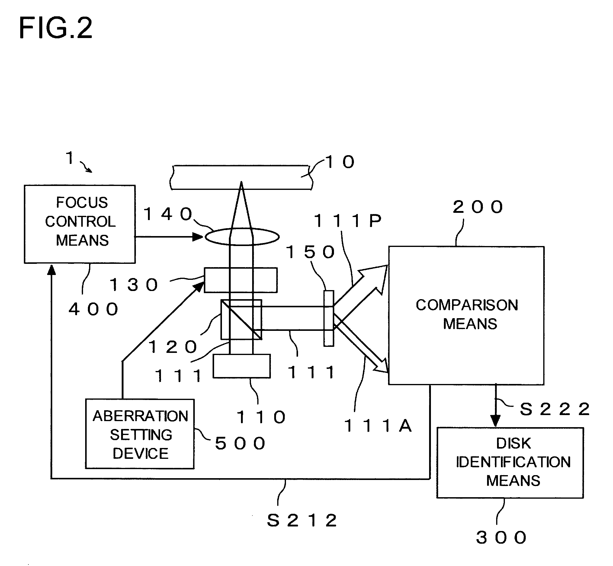
[0013] According to this configuration, light reflected from the optical disc is divided into central light and peripheral light, the time difference at a zero level between the central light focus error signal and the peripheral light focus error signal obtained from the central light and the peripheral light, respectively is detected, and a type of the optical disc is identified based on the time difference, which makes it possible to identify the optical disc by illuminating light only once. Hence, disc identification can be effected in a shorter time as compared with the technique in which an optical disc is illuminated with light while the light is sequentially switched among ones having predetermined wave lengths corresponding respectively to the types of optical discs to thereby determine whether or not the optical disc can be operated. With such an advantage, since reproduction / recording can be done quickly after insertion of the optical disc, a user can enjoy better operability. With the use of the time difference at a zero level between the central light focus error signal and the peripheral light focus error, an influence of noise is hard to be received as compared with the technique in which a disc is identified using the whole of a waveform of the focus error signal. Therefore, accurate disc identification can be performed. Since a disc is identified based on the time difference, a processing load for disc identification is smaller as compared with the technique in which the whole of a waveform of the focus error signal is used.
[0015] With this configuration, since light reflected from the optical disc is divided into central light and peripheral light and compared with each other to thereby determine a type of the optical disc based on the result of the comparison, a single light illumination enables identification of a disc. Hence, disc identification can be effected in a shorter time as compared, for example, with the technique in which an optical disc is illuminated with light while the light is sequentially switched among ones having predetermined wave lengths corresponding respectively to the types of optical discs to thereby determine whether or not the optical disc can be operated. Thus, reproduction / recording can be done quickly after the optical disc is inserted and, thereby, a user can enjoy better operability.
[0019] Preferably, the focusing operation is a focus search operation. Hence, since disc identification is performed during the focus search operation, an additional separate focusing operation for disc identification is not required. Therefore, the time from the insertion of an optical disc until reproduction / recording can be further shortened, thereby providing a user with better operability.
[0030] According to the present invention, as described above, since an identification time for an optical disc can be shortened to thereby enable reproduction / recording to be performed quickly after the optical disc is inserted, a user can enjoy a better operability. Also, according to the present invention, exact disc identification can be realized with a smaller processing load.

Problems solved by technology

With the use of the time difference at a zero level between the central light focus error signal and the peripheral light focus error, an influence of noise is hard to be received as compared with the technique in which a disc is identified using the whole of a waveform of the focus error signal.

Method used


Image

  • Optical disc device
  • Optical disc device
  • Optical disc device

Examples


Embodiment Construction

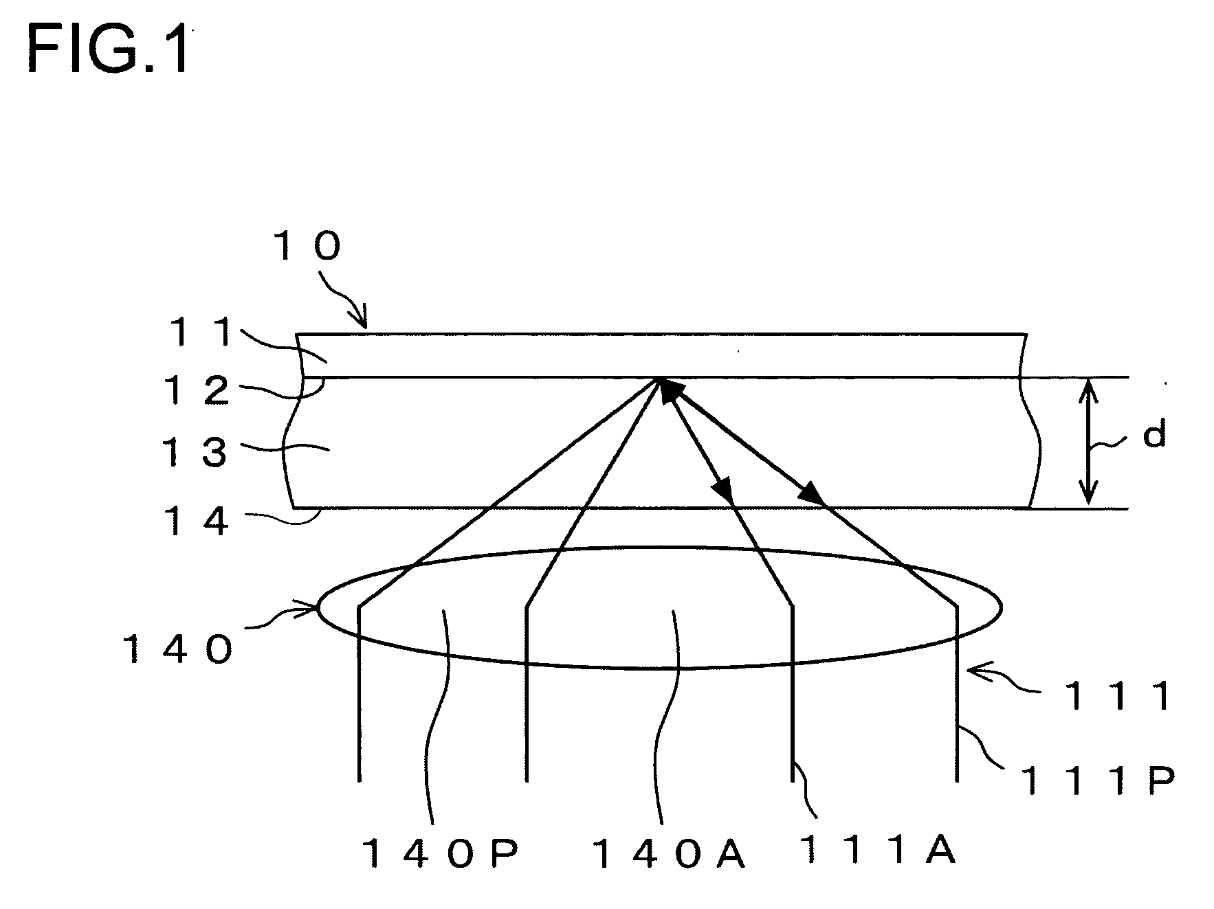
[0040] First of all, in FIG. 1, there is shown a schematic view for describing the principles of the present invention. A basic structure of an optical disc 10 such as CD (Compact Disc), DVD (Digital Versatile Disc), or BD (Blu-ray Disc), as shown in FIG. 1, includes a substrate 11, an information recording surface 12 on the substrate 11, and a protective layer 13 on the information recording surface 12. Reproduction / recording from or onto the optical disc 10 is performed by illuminating the information recording surface 12 with light 111 through an objective lens 140 from the protective layer 13 side.

[0041] When in reproduction / recording from or onto the optical disc 10, it is necessary to condense the light 111 to coincide the focus with the information recording surface 12 at which time it is further necessary to suppress or eliminate a so-called spherical aberration. The reason therefor is that the spherical aberration renders servo control such as for focusing unstable and, as...


PUM

PropertyMeasurementUnit
wavelengthsaaaaaaaaaa

Abstract

Light (111) emitted from a light source (110) is transmitted through an objective lens (140), reflected from an optical disc (10), transmitted again through the objective lens (140), and thereafter divided into central light (111A) transmitted through a central part of the objective lens (140) and peripheral light (111P) transmitted through a peripheral part of the objective lens (140) by a hologram (150). A central light FE signal (S212A) is generated from the central light (111A) and a peripheral light FE signal (S212P) is generated from the peripheral light (111P). In a focus search operation, an S-letter detector (221A) detects a time point at a zero level of the central light FE signal (S212A), and an S-letter detector (221P) detects a time point at a zero level of the peripheral light FE signal (S212P). A time difference is measured by a timer counter (222) in terms of elapsed time. Disc identification means (300) identifies a type of the optical disc (10) based on the time difference.

Description

[0001] This application is based on Japanese Patent Application No. 2005-031591 filed on Feb. 8, 2005, the contents of which are hereby incorporated by reference. BACKGROUND OF THE INVENTION [0002] 1. Field of the Invention [0003] The present invention relates to an optical disc device. In particular, the present invention relates to an optical disc identifying technique in the optical disc device. [0004] 2. Description of the Prior Art [0005] In recent years, development has been progressed in order to use plural types of optical discs such as CD (Compact Disc), DVD (Digital Versatile Disc) and BD (Blu-ray Disc) with a single optical disc device. It is necessary of such an optical disc device to identify the type of optical disc to be inserted. [0006] As an optical disc identifying technique, for example, there is a way in which an inserted optical disc is illuminated sequentially with light having each of predetermined wavelengths (for example, 750 nm, 650 nm, and 405 nm), which a...

Claims


Application Information

Patent Timeline
Patent Type & Authority Applications(United States)
IPC IPC(8): G11B7/00
CPCG11B7/1353G11B19/12
Inventor IWAMOTO, ATSUSHI
Owner FUNAI ELECTRIC CO LTD
Learn More