Positive pressure air purification and conditioning system

a technology of air purification and air conditioning system, applied in space heating and ventilation control systems, lighting and heating apparatuses, heating types, etc., can solve the problems of air flow and bring with it additional contaminants, and achieve the effect of reducing the overall air purification requirements, preventing entry of additional contaminants, and exceptional room air quality

Inactive Publication Date: 2006-08-10
MILLER GREGORY ROBERT
View PDF25 Cites 88 Cited by
  • Summary
  • Abstract
  • Description
  • Claims
  • Application Information

AI Technical Summary

Benefits of technology

[0012] The air purification unit is particularly useful in maintaining a positive pressure system or environment. A positive pressure system reduces the overall air purification requirements of a room by blocking typical sources of indoor air contamination. Typically, air flows into an enclosed space bringing with it additional contaminants. By creating a positive pressure, air flows out of the enclosed space, thereby preventing entry of the additional contaminants. By using the air purification unit to bring air in from outside the room while contemporaneously forcing air within the room to exit via predetermined path, a positive pressure is achieved. The combination of purifying air brought into the room and the positive pressure to prevent further contamination leads to exceptional room air quality.
[0013] The air purification unit is adapted to receive air from more than one source. As such, some embodiments of the air purification unit include controls to select a source of air for purification. For example, the air purification unit may receive both room air and air from an HVAC duct. The air purification unit may select the room air, air from the HVAC air stream, or some combination thereof for filtration. Source selection may be accomplished in at least two different ways. First, the air purification unit may control the amount of air drawn in from one of the inlets. This may be accomplished through the use of a grill or a damper. Second, the air purification system may adjust the speed of the air handler to draw in more or less air.

Problems solved by technology

Typically, air flows into an enclosed space bringing with it additional contaminants.

Method used


Image

  • Positive pressure air purification and conditioning system
  • Positive pressure air purification and conditioning system
  • Positive pressure air purification and conditioning system

Examples


Embodiment Construction

[0060] The following description of the preferred embodiment(s) is merely exemplary in nature and is in no way intended to limit the invention, its application, or uses.

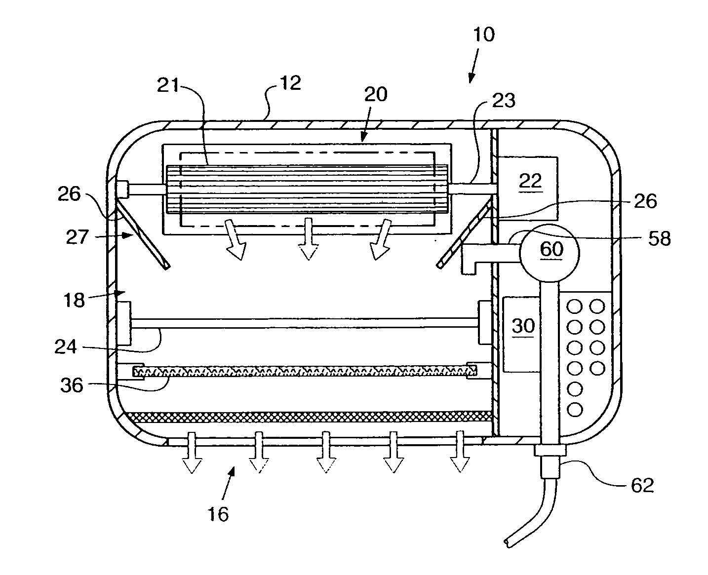
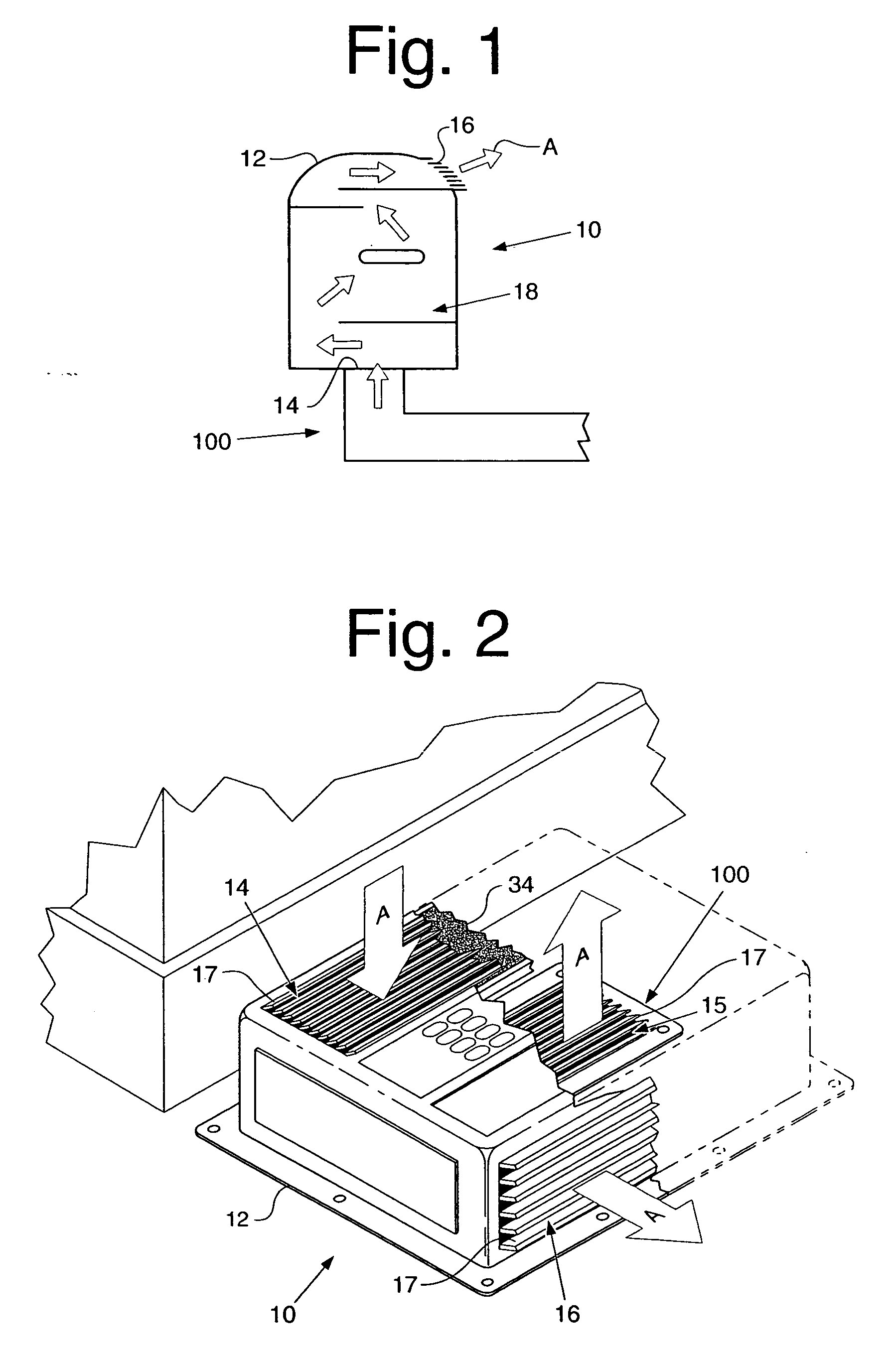
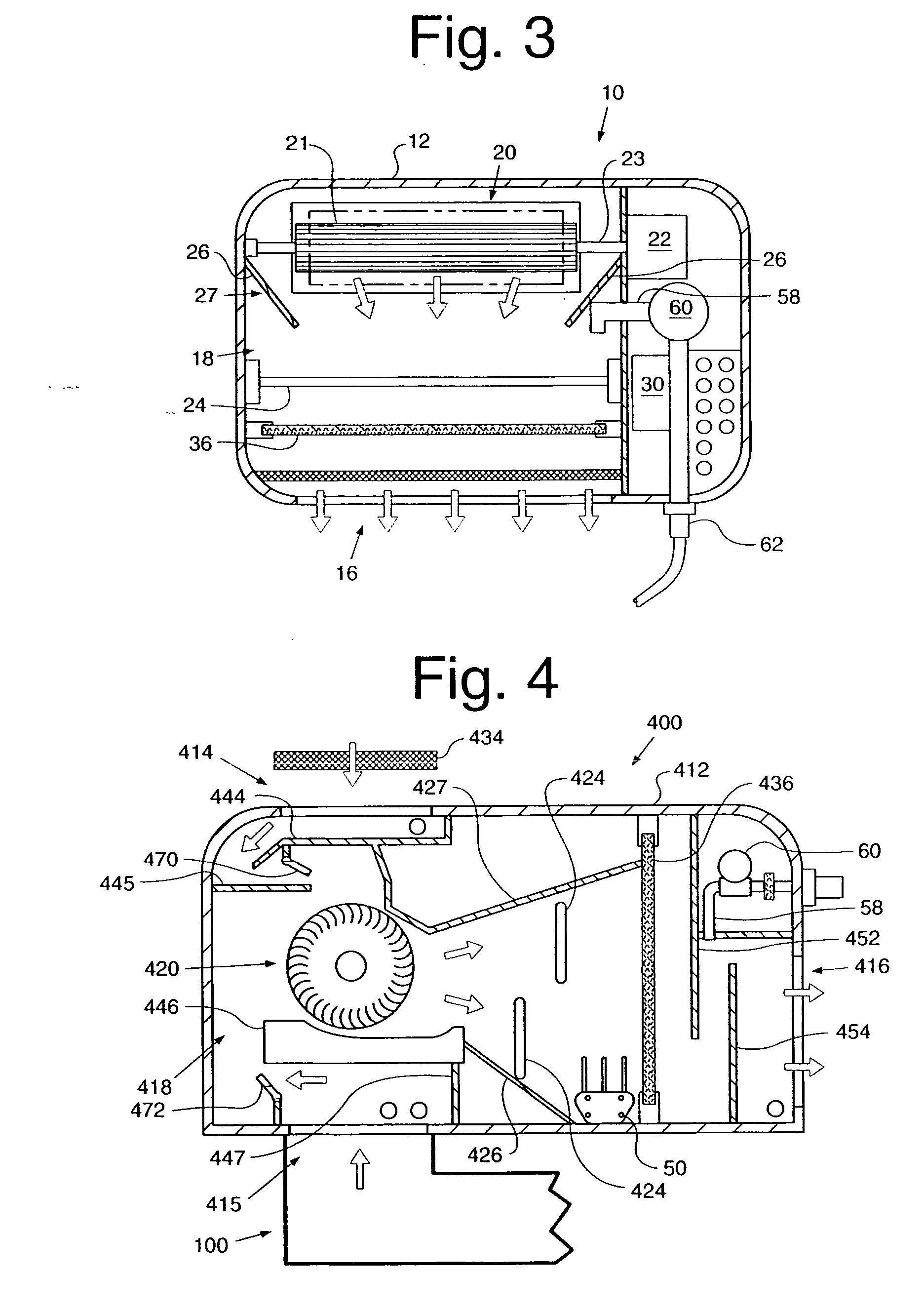
[0061] Referring to the accompanying drawings in which like reference numbers indicate like elements, FIG. 1 illustrates an air purification system 10. The air purification system 10 is used to create and sustain exceptionally high indoor air quality in a room or a series of rooms. The air purification system 10 utilizes a ventilation duct 100, such as Heating, Ventilation, and Air Conditioning (HVAC) supply and return ducts, which are commonly found in many houses and buildings. Further, the air purification system 10 may be used in a room equipped with a closable door or doors. While the preferred embodiments of the air purification system 10 are discussed in relation to a bedroom in a home, those skilled in the art would understand that the air purification system 10 could also be used in an office in a building,...


PUM

PropertyMeasurementUnit
wave lengthaaaaaaaaaa

Abstract

An air purification system utilizing an ultraviolet germicidal lamp is disclosed. The air purification system is in fluid communication with a ventilation duct. The air purification system may also be in fluid communication with the ambient air. The air purification system may incorporate an actuator for the selection of the ambient air, the ventilation duct, or both as an air source for treatment. The air purification system may also be used to obtain a positive pressure within an enclosed space.

Description

CROSS-REFERENCE TO RELATED APPLICATIONS [0001] Not applicable. BACKGROUND OF THE INVENTION [0002] 1. Field of the Invention [0003] The present invention relates generally to air cleansing devices and, more particularly, to ultraviolet irradiation and filtration devices. [0004] 2. Related Art [0005] Over the years, many devices have been used to treat the air in an attempt to purify it. A common strategy is to use an air filter to rid indoor air of biological contaminants. While this is an important element of cleaning air, this has its problems. Most filters are inadequate because many organisms pass right on through the filter due to the limitations of filter size. Also, any organisms that collect on the filter can form germ colonies that may soon contaminate passing air. Further, if the filter should be too efficient, it blocks the passage of air and creates back pressure, causing the blower to struggle to move air through the system. Moreover, even if air within a room has been t...

Claims


Application Information

Patent Timeline
Patent Type & Authority Applications(United States)
IPC IPC(8): A61L9/20
CPCA61L9/16A61L9/20F24F3/166F24F2003/1667F24F2011/0004A61M11/06A61M16/0057A61M16/0066A61M16/06A61M16/0808A61M16/10A61M16/105A61M2016/0033A61M2202/0208A61M2205/053A61M2205/3334A61M2205/3368A61M2205/3606A61M2209/10A61M2210/0618A61M2210/0625A61M16/0063A61M16/0672A61M16/101F24F8/192F24F8/22Y02A50/20
Inventor MILLER, GREGORY ROBERT
Owner MILLER GREGORY ROBERT
Why Eureka
Try Eureka