Junction box for output wiring from solar module and method of installing same

Inactive Publication Date: 2006-08-17
BP CORP NORTH AMERICA INC
View PDF3 Cites 94 Cited by
  • Summary
  • Abstract
  • Description
  • Claims
  • Application Information

AI Technical Summary

Benefits of technology

[0008] The present invention provides a junction box adapted to protect electrical connections from the “elements” wherein the connections are between outputs and respective cables and are made on a substantially flat surface. The invention is also a method for installing the junction box over the connections. The junction box of the present invention is easy to install after one or more output cables have been solde

Problems solved by technology

A problem arises in protecting the soldered connections between the terminals and the output cables in that, if left exposed, can short out or otherwise be damaged by adverse weather or atmospheric conditions.
This trapped air, in turn, can allow moisture and/or water to enter the box and attack the integrity of the connections which, in turn, can render the module inoperable.
Further, the prior art boxes are relatively large

Method used


Image

  • Junction box for output wiring from solar module and method of installing same
  • Junction box for output wiring from solar module and method of installing same
  • Junction box for output wiring from solar module and method of installing same

Examples


Embodiment Construction

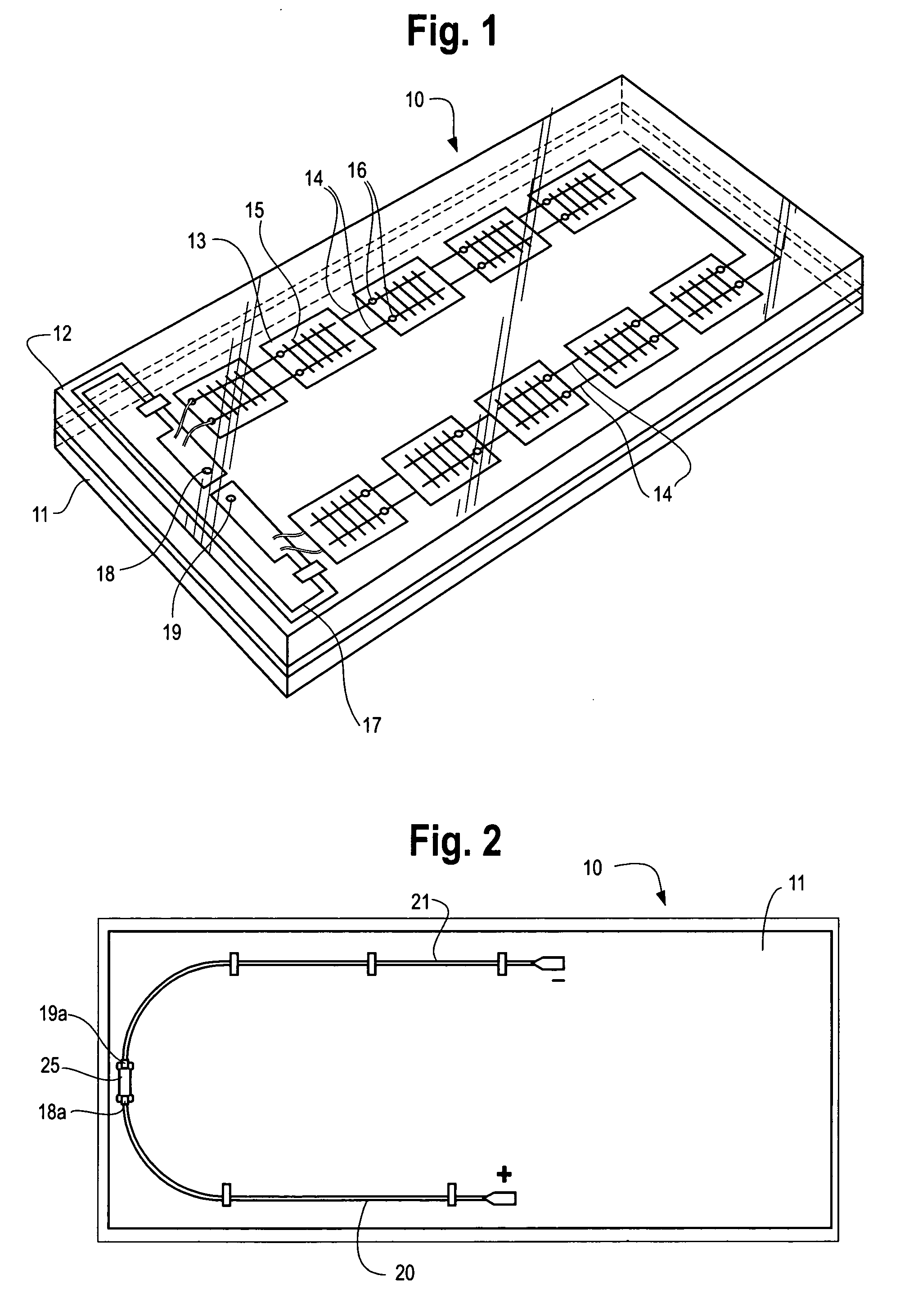
[0021] Referring now to drawings, FIG. 1 illustrates a typical photovoltaic module 10 in which the junction box of the present invention can be used. Module 10 is formed of a backing sheet 11 of any suitable material, e.g. a polymeric material, and a cover substrate 12, preferably comprised of glass or other suitable transparent material. Between substrate 12 and backing sheet 11 is sandwiched a plurality of photovoltaic cells (PV) 13 (only one numbered for clarity), electrically connected in series by wires 14. The PV cells may be of any type such as those made from multi-crystalline or mono-crystalline silicon wafers. As shown, each cell 13 has a grid-type, front electrical contact 15 (only one numbered for clarity)

[0022] Sunlight enters through substrate sheet 12 and impinges on the front side of the PV cells 13. The wires 14, which connect the cells 13 in series, are connected to a contact on the back side of the cells (not shown) and to the solder contact points 16 on the fron...


PUM


Abstract

A junction box adapted to protect soldered electrical connections between outputs and cables wherein the connections are on a flat surface (e.g. the backing sheet of a solar module) and a method for installing the box over the connections. The junction box can have a split housing that can be spread to fit over the cables before filling the housing with a sealant which, in turn, covers and protects the connections. A separate cover is then latched onto the housing.

Description

[0001] This application claims the benefit of U.S. Provisional Patent Application 60 / 652,256, filed on Feb. 11, 2005.FIELD OF THE INVENTION [0002] The present invention relates to a junction box for protecting electrical connections from the elements and in one of its aspects relates to a junction box adapted to be positioned over and protect the connections between the terminal output wires of a solar module and their respective output cables and a method of installing the junction box over these connections. BACKGROUND OF THE INVENTION [0003] In recent years, considerable advances have been made in photovoltaic (PV) cells or the like for directly converting solar energy into useful electrical energy. Typically, a plurality of these photovoltaic cells are encased between a transparent sheet (e.g. glass, plastic, etc.) and a sheet of backing material, to thereby form a flat, typically rectangular-shaped solar module (sometimes also called “laminate” or “panel”) of a manageable size ...

Claims


Application Information

Patent Timeline
IPC IPC(8): H01L31/042
CPCH01R4/70H02S40/34H01R13/5216Y02E10/50
Inventor LARES, JOSEPH G.AMIN, DINESH S.
Owner BP CORP NORTH AMERICA INC
Why Eureka
Try Eureka