Lubricant dispenser

a technology of lubricant dispenser and dispenser body, which is applied in the direction of engine lubrication, liquid/fluent solid measurement, volume measurement, etc., can solve the problems of complicated protective measures, complicated gas cell production, and harm to the environmen

Active Publication Date: 2006-08-17
PERMA TEC
View PDF18 Cites 17 Cited by
  • Summary
  • Abstract
  • Description
  • Claims
  • Application Information

AI Technical Summary

Benefits of technology

[0012] The switch of the lubricant dispenser is preferably configured as a rotary switch and disposed in the face-side opening of the outer ring. Electrical connections for the power source and the gas cell are disposed at the rotary switch. In particular, a conductor track can be disposed on the inside of the rotary switch. The conductor track forms an electrical connection between the power source and the gas cell, with a resistance that is dependent on the angle of rotation of the switch. The contact between the rotary switch and the power source can be produ

Problems solved by technology

The electrolyte fluid, e.g. an aqueous sodium azide solution, is a substance that is harmful to the environment and hazardous to health.
As a result, complicated protective measures are required during production of the gas cell and the satur

Method used


Image

  • Lubricant dispenser
  • Lubricant dispenser
  • Lubricant dispenser

Examples


Embodiment Construction

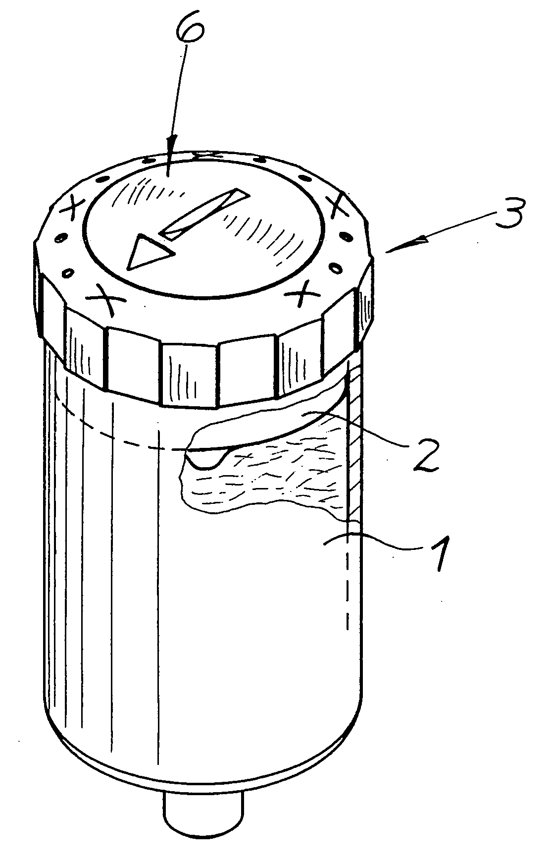
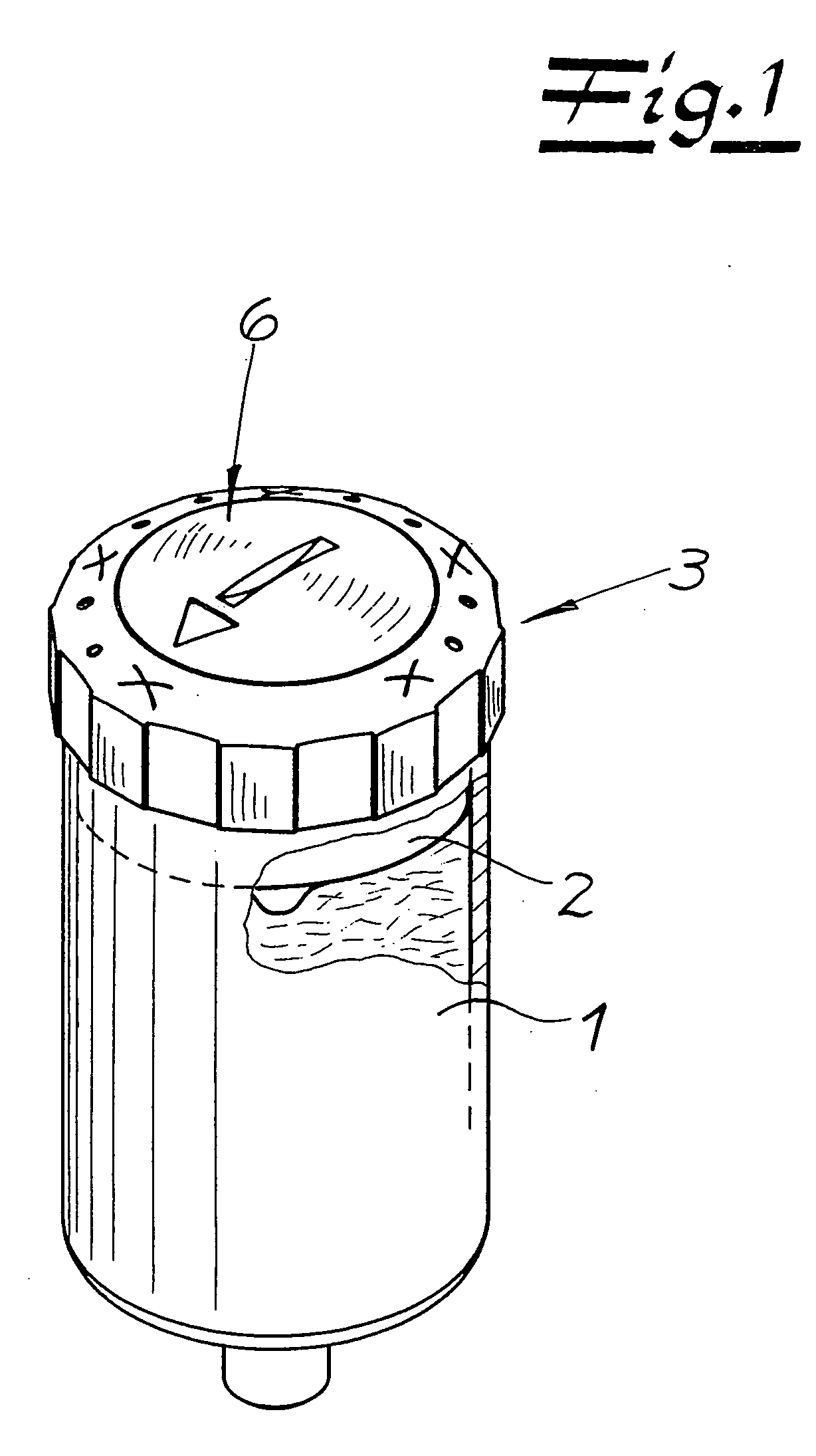
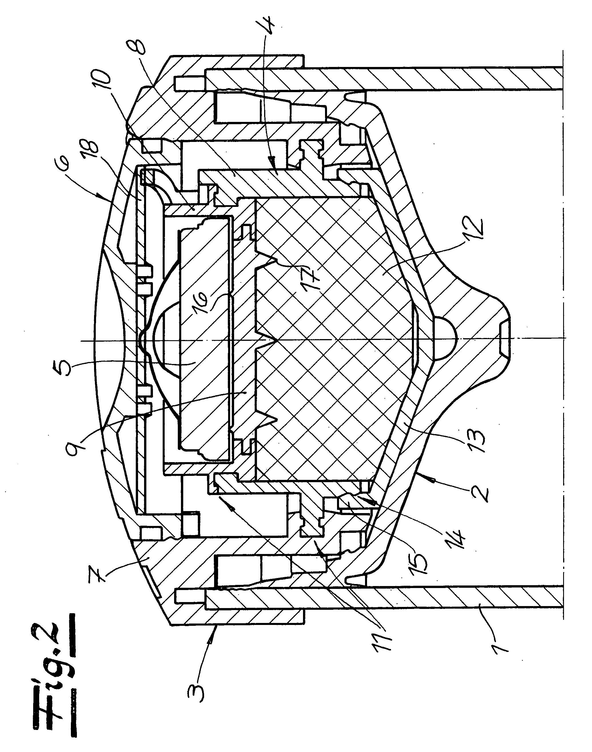
[0018] The fundamental structure of the lubricant dispenser shown in the drawings includes a lubricant container 1 that has an outlet opening for lubricant, a piston 2 disposed on the lubricant container 1, and a cap 3 connected with the lubricant container, having a device for generating a gas that impacts the piston. The device for gas generation has a gas cell 4 with an electrolyte fluid and electrodes for electrochemical gas generation, a power source 5 in the form of a button battery, as well as an electrical connection between the power source and the electrodes with a switch 6.

[0019] As particularly evident from FIG. 2, cap 3 is a plastic injection-molded part produced in one piece, formed from several parts, using the multi-component injection-molding method. This part is made up of an outer ring 7 made of insulation material and an insert that forms gas cell 4, having two electrically conductive wall regions 8, 9 electrodes, as well as having an intermediate piece 10 that ...


PUM


Abstract

A lubricant dispenser includes a lubricant container that has an outlet opening for lubricant, a piston disposed in the lubricant container, and a cap connected with the lubricant container, having a device for generating a gas that impacts the piston. The device for gas generation has a gas cell with an electrolyte fluid and electrodes for electrochemical gas generation, a power source, as well as an electrical connection between the power source and the electrodes with a switch. The cap is a plastic injection-molded part produced in one piece, formed from several parts, using the multi-component injection-molding method, which part is made of an outer ring made of insulation material and an insert that forms the gas cell, having two electrically conductive wall regions as electrodes, as well as having an intermediate piece that separates the conductive regions. The insert contains a sponge saturated with electrolyte fluid, and is closed off with a plastic lid.

Description

CROSS REFERENCE TO RELATED APPLICATIONS [0001] Applicant claims priority under 35 U.S.C. §119 of German Application No. 10 2005 004 456.5 filed on Feb. 1, 2005. BACKGROUND OF THE INVENTION [0002] 1. Field of the Invention [0003] The present invention relates to a lubricant dispenser. The dispenser has a lubricant container that has an outlet opening for lubricant, a piston disposed in the lubricant container, and a cap connected with the lubricant container. The cap has a device for generating a gas that impacts the piston. The device for gas generation has a gas cell with an electrolyte fluid and electrodes for electrochemical gas generation, a power source, as well as an electrical connection between the power source and the electrodes with a switch. When current flows, a gas is generated electrochemically, by means of which a pressure builds up on the back side of the piston. The pressure build-up results in an advance of the piston, by means of which lubricant is displaced out o...

Claims


Application Information

Patent Timeline
IPC IPC(8): F16N13/00
CPCF16N11/08F16N11/10
Inventor GRAF, WALTER
Owner PERMA TEC
Why Eureka
Try Eureka