
Vehicle ride control system

a ride control and suspension technology, applied in the direction of resilient suspensions, vehicle springs, vehicle components, etc., can solve the problems of difficult to fit into the space available in existing vehicles, commercial acceptance of ride control suspension systems is somewhat limited, and the integration of wheel position sensors requires complicated algorithms, etc., to achieve simple and effective ride control, easy installation, and convenient fit

Inactive Publication Date: 2006-08-17
SPARTAN MOTORS CHASSIS
View PDF23 Cites 70 Cited by
  • Summary
  • Abstract
  • Description
  • Claims
  • Application Information

AI Technical Summary

Benefits of technology

[0010] The present invention provides a simple and effective ride control suspension system. The suspension control units of the present invention require only a single pressure regulator and are therefore relatively small allowing the unit to more readily fit into the packaging constraints of existing vehicles. The integrated nature of the various elements of the fluid control circuit provides a unit that is easily installed without the need for laborious on-vehicle assembly. The use of external wheel position sensors avoids complexity inherent in preexisting systems, thereby reducing the overall cost of installation and maintenance. The use of a single central controller simplifies operation and maintenance, and therefore also reduces the overall cost of installation and maintenance of the system.

Problems solved by technology

Although existing vehicle ride control suspension systems can provide marked improvement in handling, comfort and control of a vehicle, experience has revealed that the more effective conventional systems are excessively large and difficult to fit into the space available in existing vehicles.
As a result, the commercial acceptance of ride control suspension systems has been somewhat limited.
As a result of the expansion and contraction in oil volume that occurs with changes in temperature, the integrated wheel position sensor requires complicated algorithms to provide proper compensation for temperature-based changes in oil volume.
In combination, the components of these prior systems are relatively bulky and rather difficult to fit into the packaging constraints of many conventional vehicle designs.
Further, at least some of the components of these prior systems operate at a high level of complexity, thereby increasing cost and potentially reducing reliability.
The systems are also relatively expensive to manufacture and assemble, thereby further reducing the commercial appeal of ride control suspension systems.

Method used


Image

  • Vehicle ride control system
  • Vehicle ride control system
  • Vehicle ride control system

Examples


Embodiment Construction

I. Overview.

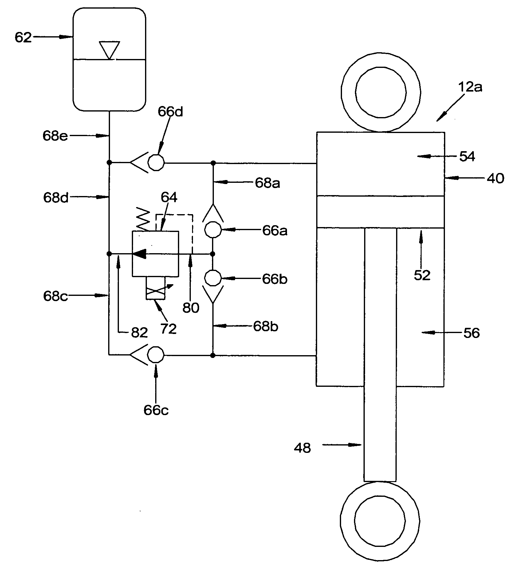
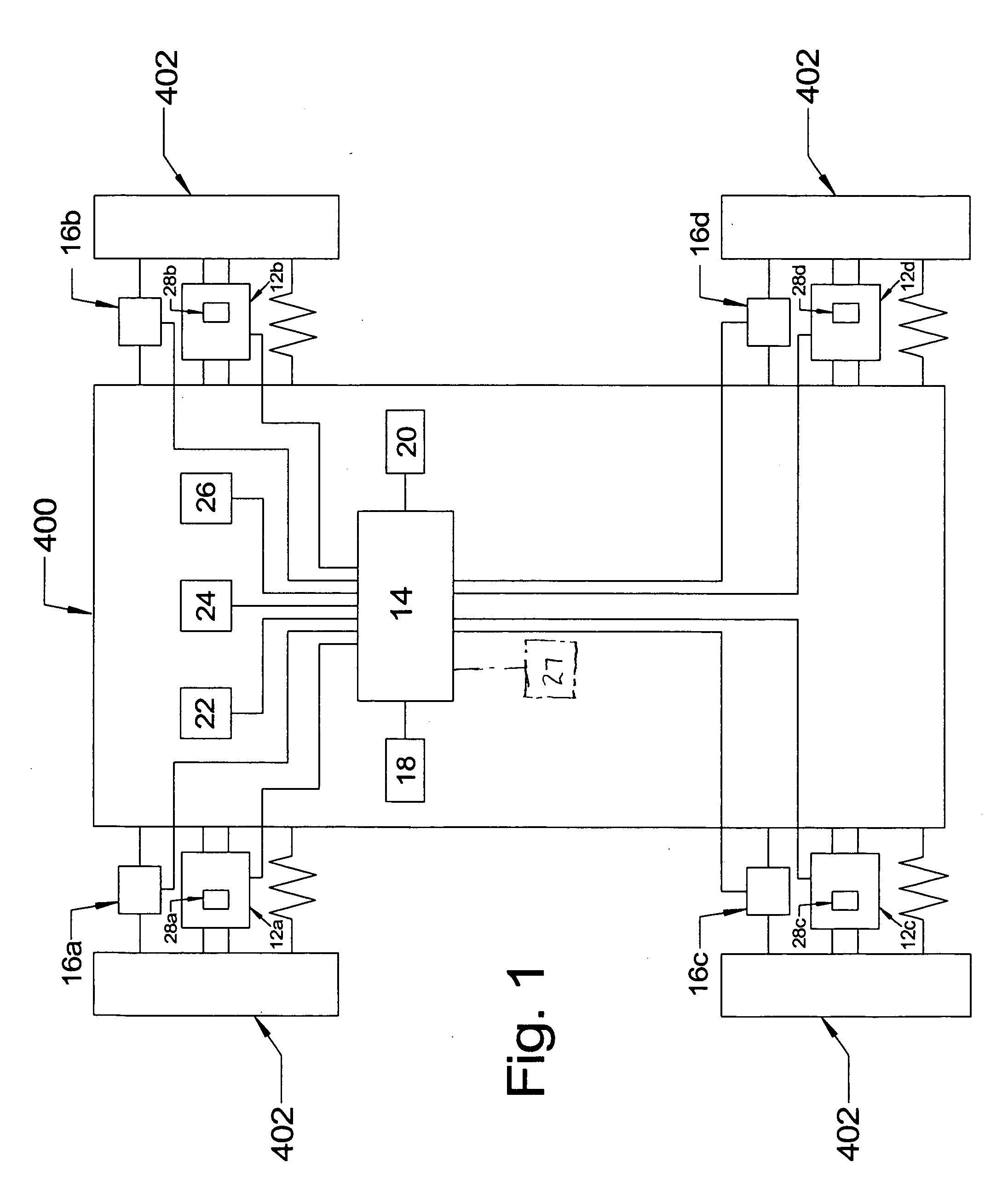
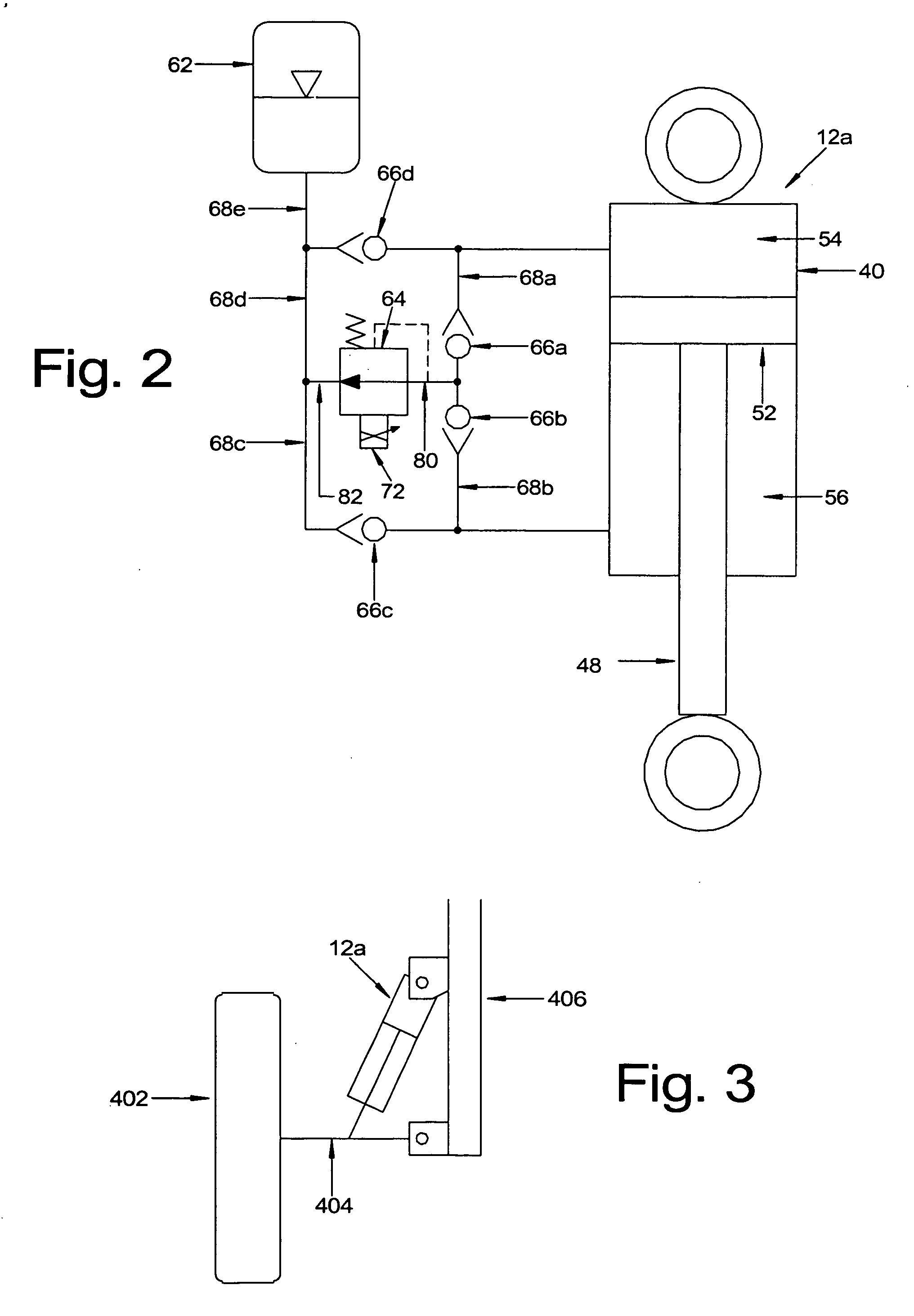
[0041] A vehicle ride control suspension system in accordance with an embodiment of the present invention is shown schematically in FIG. 1 and generally designated 10. In this embodiment, the system 10 generally includes four suspension control units 12a-d (one located at each wheel), a plurality of sensors (e.g. wheel position sensors 16a-d , steering angle sensor 18, lateral and longitudinal axes accelerometer 20, brake sensor 22, ignition sensor 24, speed sensor 26 and solenoid feedback sensors 28a-d) disposed at various locations about the vehicle, and a central controller 14 for processing the input from the various sensors and separately controlling operation of the plurality of suspension control units 12a-d. The various sensors provide information indicative of various conditions encountered by the vehicle, such as road irregularities, cornering, braking and acceleration. In operation, the central controller 14 obtains input from the various sensors and separatel...


PUM


Abstract

A ride control suspension control system having suspension control units with a damper and a single pressure regulator that controls dampening in both the compression and rebound chambers of the damper. The fluid control circuit may include a plurality of check valves that coordinate the flow of fluid to and from both chambers through the pressure regulator. In one embodiment, the system includes a central controller that receives input from a variety of sensors and directly controls operation the pressure regulators in each of the suspension control units without the need for any remote processors. The ride control suspension system may also include wheel position sensors that are external to the accumulator.

Description

BACKGROUND OF THE INVENTION [0001] The present invention relates to vehicle ride control systems and more particularly to a control system for controlling vehicle ride in real-time. [0002] A variety of vehicle ride control systems have been developed to provide real-time control over vehicle ride. For example, ride control systems have been developed to adjust in real-time the damping forces of a damper, such as a hydraulic shock, during both compression and rebound in response to road irregularities and other vehicle conditions. These adjustments are made as a function of a variety of factors, including a variety of sensed variables that are indicative of acceleration, deceleration, cornering, road impacts and other similar vehicle characteristics. One system designed to generate a constant compression and / or rebound force at a wheel is disclosed in PCT International Publication No. WO 96 / 05975, which is entitled Computer Optimized Adaptive Suspension System and Method Improvements...

Claims


Application Information

Patent Timeline
IPC IPC(8): B60G17/02B60G11/26
CPCB60G15/12B60G17/0152B60G17/0165B60G17/08B60G2202/154B60G2202/24B60G2400/102B60G2400/104B60G2400/204B60G2400/252B60G2400/39B60G2400/41B60G2500/10B60G2500/106B60G2600/08B60G2800/80
Inventor WILDE, MICHAEL D.HART, JOHN G.KUMAR, ABHINAV
Owner SPARTAN MOTORS CHASSIS
Learn More