Security element

Inactive Publication Date: 2006-08-17
GIESECKE & DEVRIENT GMBH
View PDF7 Cites 34 Cited by
  • Summary
  • Abstract
  • Description
  • Claims
  • Application Information

AI Technical Summary

Benefits of technology

[0020] In the case of an embossed hologram the effect according to the invention can be obtained, for example, by the subareas having no or a visually less recognizable diffraction structure and by the reflection layer being present both in the area of the diffraction structure and in the area of the not diffractive subareas. Since the subareas have no or a worse recognizable diffraction structure, they actually do not contribute to the reconstruction of the diffractive image and therefore due to the changed reflection conditions are recognizable under those specific viewing conditions, under which also the diffractive image is recognizable for the viewer. Under all other viewing conditions the entire area appears as an almost structureless area. The individual information represented by the subareas thus cannot be recognized by the viewer upon viewing from other than the specific viewing conditions.
[0021] The subareas which are free of any diffraction structures ca

Problems solved by technology

Such effects cannot be reproduced with the usual and widespread copying techniques and printing te

Method used


Image

  • Security element
  • Security element
  • Security element

Examples


Example

EXAMPLE 1 (FIG. 4, 5)

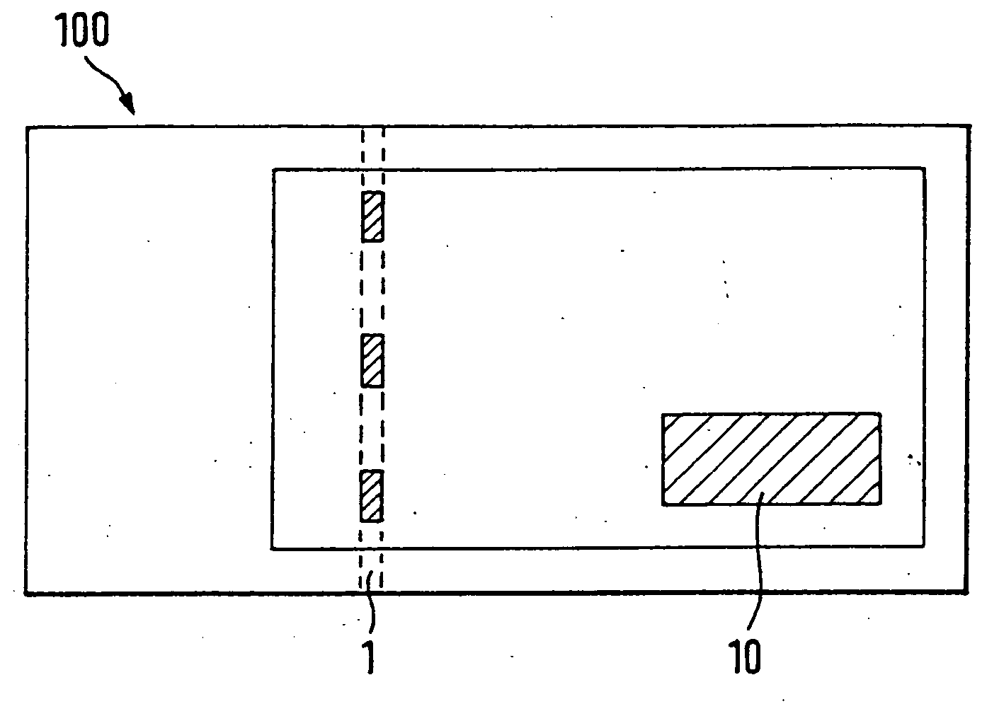
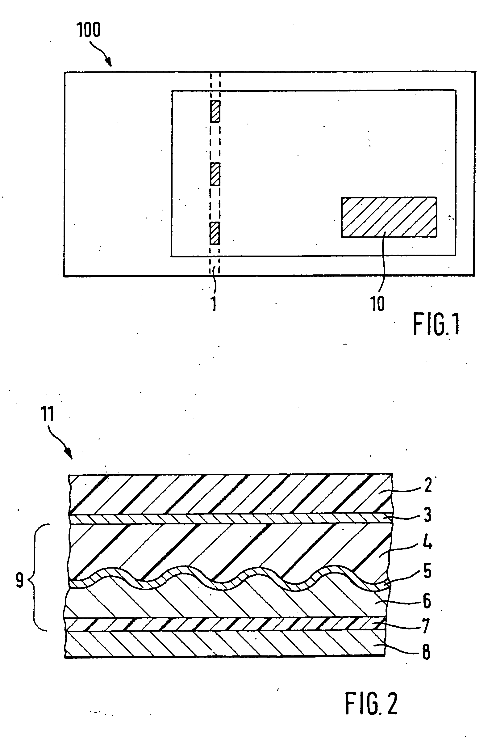
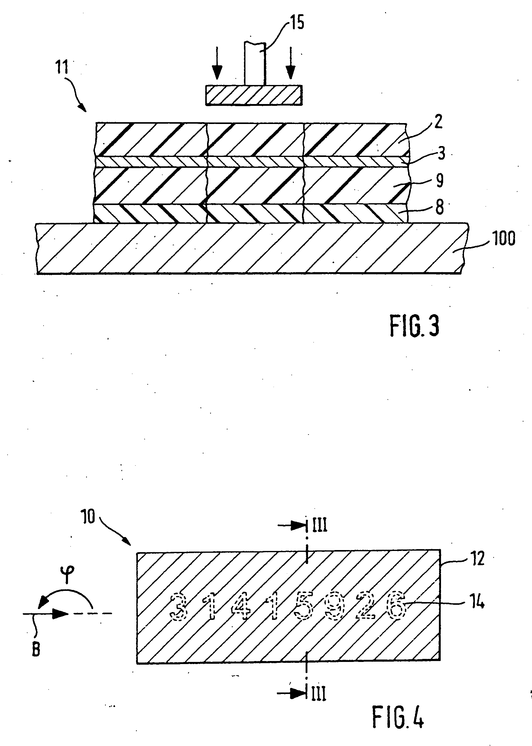
[0069]FIGS. 4 and 5 show an embodiment of the security element 10 in plan view and in cross section, wherein the security element 10 has only one self-contained area 12 with a diffraction structure. As already explained, the specific design of this diffraction structure is irrelevant for the invention. Essentially, the diffraction structure has to have viewing angles wherein the diffractive effect is reconstructed on the incidence of light, while under other viewing angles this diffractive effect is not perceptible or only diffusely perceptible. Arrow B in FIG. 5 here stands for the viewing angles wherein the diffractive effect is recognizable. I.e., upon viewing the area 12 in a narrow angle range around this predetermined viewing direction B the viewer perceives the diffractive effect produced by the diffraction structure, while under other viewing angles this diffractive effect is not perceptible or only diffusely perceptible.

[0070] The viewing direction B ...

Example

EXAMPLE 2 (FIG. 4, 5)

[0079] According to a further embodiment of the invention the security element 10 has the layer structure as shown in FIG. 5. However, in this case the reflection layer 22 is made of a material contrasting to the reflection layer 26, preferably of a differently colored metal. If the reflection layer 26 is an aluminum layer, for the reflection layer 22 for example a copper layer can be used. In this case due to the different colors of the two reflection layers 22, 26 upon perpendicular viewing to the viewer the gaps 25 appear as a not diffractive contrast image. The viewer therefore can recognize the information content of the contrast image, in the present example the serial number, even upon perpendicular viewing as copper-colored areas against a silver background. Since the layer 24 is relatively thin, the viewer gets the impression that the gaps 25 are filled with a different material, in the present case copper. Moreover, as already explained in the above e...

Example

EXAMPLE 3 (FIG. 6, 7)

[0081]FIGS. 6 and 7 show further embodiments of the security element according to the invention in top view. These security elements are characterized in that they have two self-contained areas, which preferably directly adjoin each other.

[0082]FIG. 6 shows a security element 30, which has two rectangular areas 32A, 32B disposed one above the other, both having a diffraction structure. The image contents reconstructed by the respective diffraction structures can be identical for the two areas but they may also differ from each other. In any case the viewing angles of the diffraction structures disposed in the areas32A, 32B have to differ from each other. In the shown example the diffraction structure disposed in the area 32A is only recognizable upon oblique viewing from the left (arrow L), while the diffraction structure disposed in the area 32B is recognizable only upon oblique viewing from the right (arrow R). According to the invention the areas 32A, 32B h...


PUM

PropertyMeasurementUnit
Lengthaaaaaaaaaa
Widthaaaaaaaaaa
Widthaaaaaaaaaa

Abstract

The invention relates to a security element, preferably for documents of value, which at least has one area with a diffraction structure, which under specific viewing conditions reconstructs a diffractive image. This area has subareas, which do not take part in the reconstruction of the diffractive image, and which represent a recognizable information. Essential is that the information represented by the subareas is recognizable mainly only under the viewing conditions, under which the diffractive image can be perceived.

Description

CROSS-REFERENCE TO RELATED APPLICATION [0001] This application is a National Phase of International Application Serial No. PCT / EP2004 / 008111, filed Jul. 20, 2004.BACKGROUND OF THE INVENTION [0002] 1. Field of the Invention [0003] The invention relates to a security element, preferably for documents of value, which at least has one area with a diffraction structure, which under specific viewing conditions reconstructs a diffractive image, wherein the area has subareas, which do not take part in the reconstruction of the diffractive image, and which represent a recognizable information. The invention further relates to a data carrier with such a security element, an embossing cylinder and a method for producing such a security element or document of value. [0004] 2. Description of the Background Art [0005] Documents, in particular documents of value and identification documents, but also commercial goods and consumer durables or their packagings for the purpose of preventing forgeries...

Claims


Application Information

Patent Timeline
IPC IPC(8): B32B1/00B42D15/00B42D15/10
CPCB41M3/148Y10T428/24802G03H1/0244G03H1/0256G03H1/265G03H2001/2273G03H2001/2615G03H2001/303G03H2240/55G03H2250/10G03H2250/36G03H2250/40G03H2250/42B42D2033/10B42D2033/24B42D25/41B42D25/43B42D25/00B42D25/324B42D25/328Y10T428/24628G03H1/0011B42D25/425B42D25/29
Inventor KAULE, WITTICHMUECK, HAJOHARMS, SIEGFRIED
Owner GIESECKE & DEVRIENT GMBH
Why Eureka
Try Eureka