Vibrator array, manufacturing method thereof, and ultrasonic probe

Active Publication Date: 2006-08-17
FUJIFILM CORP +1
View PDF10 Cites 12 Cited by
  • Summary
  • Abstract
  • Description
  • Claims
  • Application Information

AI Technical Summary

Benefits of technology

[0013] According to the present invention, the lower part of the side face of each vibrator is surrounded by the bond material used for bonding the vibrators to the base plate, so that vibration of the vibrator in the width directi

Problems solved by technology

There is a problem that such width directional vibrations unstabilize the vibration action of each piezoelectric element in the thickness direction and thus negatively influence acoust

Method used


Image

  • Vibrator array, manufacturing method thereof, and ultrasonic probe
  • Vibrator array, manufacturing method thereof, and ultrasonic probe
  • Vibrator array, manufacturing method thereof, and ultrasonic probe

Examples


Embodiment Construction

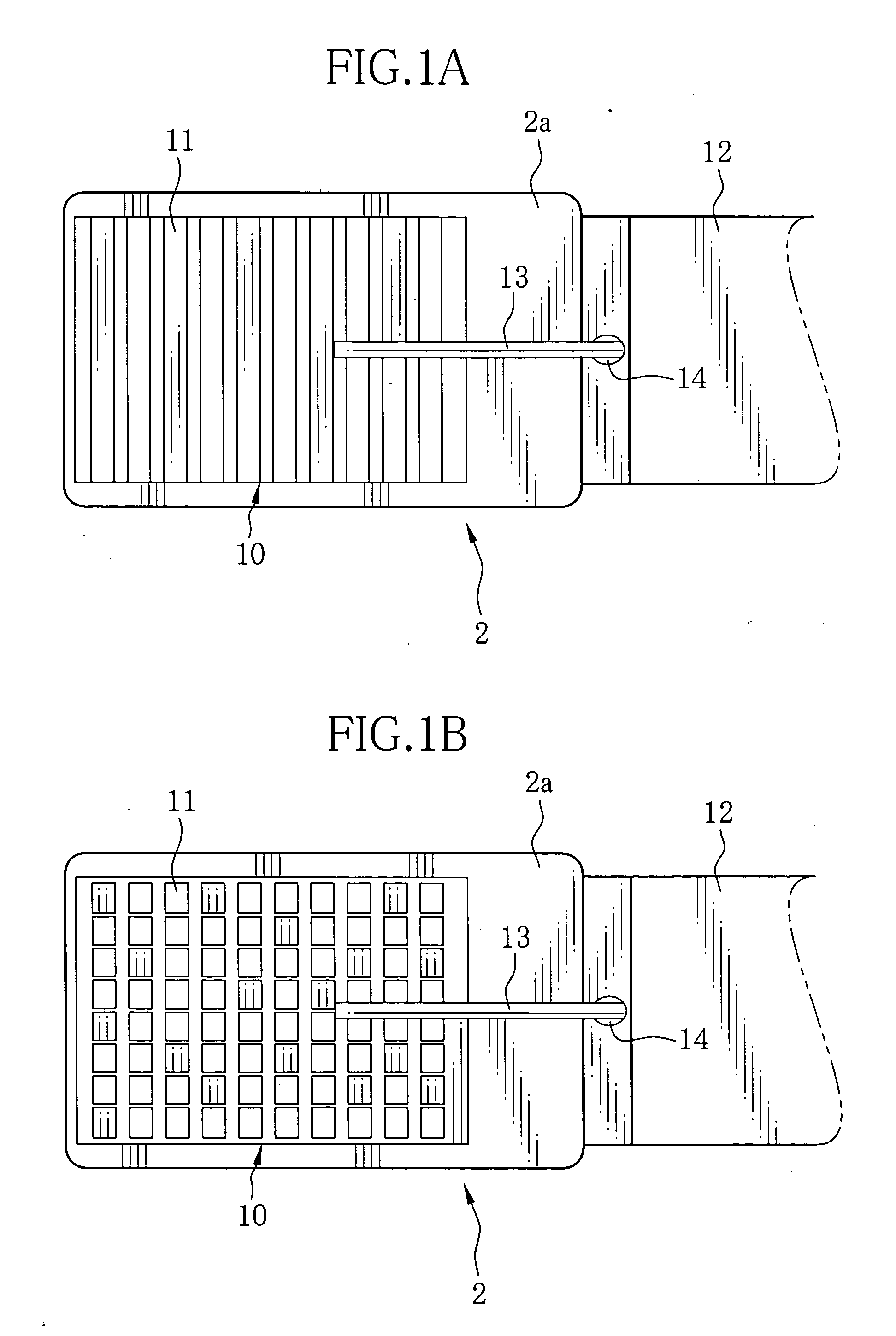
[0029] In FIGS. 1A and 1B, an ultrasonic transducer array 10 of convex electronic scanning type is disposed at a tip 2a of an ultrasonic probe 2. In the ultrasonic transducer array 10, a plurality of ultrasonic transducers 11 is arranged in either one-dimensional array state as shown in FIG. 1A or two-dimensional array state as shown in FIG. 1B. In the ultrasonic transducer array 10, a backing material 21 (see FIG. 2) is bonded to a curved surface of a supporting member 20 (see FIG. 2) which is cylindrically formed.

[0030] An imaging device for capturing optical image of an internal body part is mounted in a sheath 12 connected to the ultrasonic transducer array 10. The imaging device includes an optical system mounted to the sheath 12 and an image sensor disposed inside the sheath 12. The sheath 12 is provided with an exit end of a light guide for illuminating the internal body part. A channel for a wearing needle 14 is provided at the central part of the sheath 12. Array wiring ca...


PUM

PropertyMeasurementUnit
Fractionaaaaaaaaaa
Thicknessaaaaaaaaaa
Electrical conductivityaaaaaaaaaa

Abstract

In an ultrasonic transducer array, a plurality of vibrators arranged in an array is bonded to a base plate by bond material. The bond material bonds the bottom of the each vibrator to the base plate in a manner to surround lower part of the side face of the vibrator. A filling material is filled in between the vibrators. The filling material has a multi-layer structure of different rigidity. In a double layer structure of the filling material, it is preferable that thickness ratio of layer of filling material at the base plate side (lower side) to the other layer of the filling material is 1:1 to 1:3. Preferably, a beam is provided for connecting the side faces of the adjacent vibrators.

Description

FIELD OF THE INVENTION [0001] The present invention relates to a vibrator array having a base plate on which a plurality of vibrators is arranged in an array manner, and relates to a manufacturing method thereof and an ultrasonic probe having the vibrator array. BACKGROUND OF THE INVENTION [0002] An ultrasonic transducer array built in an ultrasonic probe is known as a vibrator array having a plurality of vibrators arranged in an array manner on a base plate. The ultrasonic transducer array includes a backing material as a base plate, piezoelectric elements as vibrators, an electrode, and an acoustic impedance matching layer. [0003] In manufacturing of the ultrasonic transducer array, a wafer of, for example, PZT (lead zirconium titanate) which is a material of the piezoelectric elements is bonded to the backing material by an adhesive. After the electrode, the acoustic impedance matching layer and the like are stacked on the wafer, grooves are made on the wafer by dicing process at...

Claims


Application Information

Patent Timeline
IPC IPC(8): H01L41/08B32B37/00
CPCB06B1/0629G10K11/004Y10T156/1089Y10T156/1052Y10T29/42
Inventor OSAWA, ATSUSHI
Owner FUJIFILM CORP
Why Eureka
Try Eureka