Split flex cable

a flex cable and cable technology, applied in the field of flex cables, can solve the problems of increasing increasing the manufacturing cost, and reducing the flexibility of the flex cable, so as to reduce the width of the combined cable and reduce the thickness of each cabl

Inactive Publication Date: 2010-04-08
GLOBALFOUNDRIES INC
View PDF2 Cites 9 Cited by
  • Summary
  • Abstract
  • Description
  • Claims
  • Application Information

AI Technical Summary

Benefits of technology

[0021]In another exemplary aspect of the invention, the number of buses in the first cable may be the same as or different from the number of buses in the second cable, on condition that the first and second cables jointly include the required total number of buses for the interconnection between the two circuit boards. The buses of each cable may be disposed on the same layer so as to reduce a thickness of each cable, or may be disposed on a plurality of layers so as to meet a width restraint of each cable. Thus, the numbers of layers of the first cable may be the same as or different from that of the second cable. The width of the first cable may be the same as that of the second cable. Further, the main cable portions of the first and second cables can be stacked together in a thickness direction of the cable, so as to reduce a width of the combined cables.

Problems solved by technology

In case of a complex system, more pins are required in the VHDM connector assembly, and a large number of vias and a large length of signal wirings are required in the flex cable, resulting a significant increase in the width of the flex cable or in the number of layers on a flex cable.
However, such an increased width WC1 may exceed the allowable overall width of the flex cable, increase the manufacturing cost, and reduce the flexibility of the flex cable.
However, this configuration also requires increased number of layers in a single flex cable.
A higher number of layers on flex cables increase cost, negatively affect manufacturability and reliability, and result in more stiff cables that do not meet flexibility or other mechanical packaging requirements.
However, so as to dispose those four bus lines on a single signal layer, the bus B54 necessarily cross the buses B51 and B52, thereby making it impossible to use a cable with a single layer.
This increased number of layers reduces the flexibility of the flex cable.
Thus, the flex cable 50 should have an additional space for such crossovers, resulting an associated bad SI impact on the flex cable 50.
Thus, each split part should be formed as an integrated element that has the same length as an unsplit connecting portion of the flex cable, thereby limiting design flexibility.
Moreover, such a flex cable split in its length direction does not give any solution to the layer number increase in the flex cable for connecting a multi-drawer system.

Method used


Image

  • Split flex cable
  • Split flex cable
  • Split flex cable

Examples


Embodiment Construction

[0038]The invention will now be described in more detail by way of example with reference to the embodiments shown in the accompanying figures. It should be kept in mind that the following described embodiments are only presented by way of example and should not be construed as limiting the inventive concept to any particular physical configuration.

[0039]Further, if used and unless otherwise stated, the terms “upper”, “lower”, “front”, “back”, “over”, “under”, and similar such terms are not to be construed as limiting the invention to a particular orientation. Instead, these terms are used only on a relative basis.

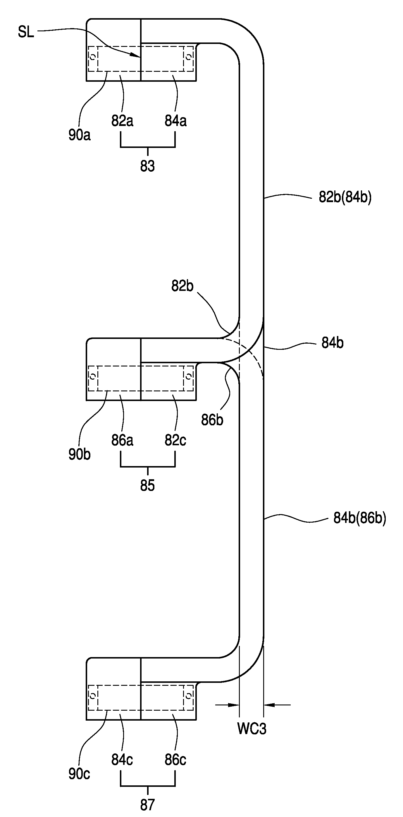
[0040]FIG. 6 is a partial top plan view of a connecting unit 60 of a cable assembly, according to an exemplary embodiment of the invention. The connecting unit 60 is split into two separate parts, including a first connecting part 62a and a second connecting part 62b.

[0041]Because the two connecting parts 62a and 62b are separated from each other, each connecting part may...


PUM

PropertyMeasurementUnit
widthaaaaaaaaaa
lengthaaaaaaaaaa
lengthaaaaaaaaaa

Abstract

A cable assembly for interconnecting a plurality of circuit boards together by using a connector assembly connected to each of the circuit boards. The cable assembly includes a first cable having a first end part and a second cable having a second end part. A first periphery of the first end part has a plurality of first half vias that collectively form a column along a width direction of the connector assembly. A second periphery of the second end part has a plurality of second half vias that collectively form a column along the width direction of the connector assembly. The first and second end parts are coupled together to form a connecting unit, such that the first half vias and the second half vias are joined together to form full vias.

Description

BACKGROUND OF THE INVENTION[0001]1. Field of the Invention[0002]The invention relates to a flex cable for interconnecting together a plurality of printed circuit boards through a connector assembly, and in particular, to a split flex cable that is coupled to the connector assembly, thereby providing an increased electrical performance and enhanced mechanical flexibility.[0003]2. Background Information[0004]Cables typically are coupled with an electronic connector assembly at opposing ends that are matable with a printed circuit board of electronic devices. Such a cable connector assembly is well known in the connector assembly art and includes a universal serial bus (USB)-type connector assembly, a parallel connector assembly, a serial connector assembly, a VHDM (very high density metric) connector assembly, and the like. The VHDM connector assembly may be used for a high-density connection between electronic devices.[0005]In computer systems, for example, flex cables having connect...

Claims


Application Information

Patent Timeline
Patent Type & Authority Applications(United States)
IPC IPC(8): H01B7/08H02G1/12H01R12/24
CPCH05K1/0219Y10T29/49174H05K1/147H05K1/189H05K3/3447H05K3/363H05K2201/041H05K2201/058H05K2201/09181H05K2201/09618H05K2201/10189H01R12/52H01R12/778H01R12/613H01R12/79Y10T29/4922H05K1/118Y10T29/49194H01R12/59H01R12/78H01R43/01H05K3/36
Inventor BRAUN, DAVID J.CLARK, MARK G.DANGLER, JOHN R.DOYLE, MATTHEW S.KIDD, THOMAS D.STOLL, JASON T.
Owner GLOBALFOUNDRIES INC
Why Eureka
Try Eureka