Supercharge Your Innovation With Domain-Expert AI Agents!

Numerical control unit

Inactive Publication Date: 2006-08-17
FANUC LTD
View PDF6 Cites 8 Cited by
  • Summary
  • Abstract
  • Description
  • Claims
  • Application Information

AI Technical Summary

Benefits of technology

[0005] The present invention provides a numerical control unit capable of low-cost, energy-efficient, centralized management of various elements (various components) in a machine tool cabinet, thereby facilitating identification of the location of a malfunction and thus reducing down time.
[0009] In the present invention, alarm information and status information relating to the elements is transmitted to a numerical controller wirelessly through wireless communications tags (wireless tags), thus enabling centralized management of the elements in the cabinet to be carried out in an energy-efficient manner at the numerical controller. In addition, the present invention obviates the need for complicated wiring inside the cabinet, thus providing a cost advantage as well.

Problems solved by technology

However, there is no concept of centralizing management of element alarm information within the actual cabinet.
However, any attempt to implement centralized management of most element alarm information by expansion of this technique necessitates coupling all the elements by wire, which complicates the internal wiring of the cabinet and increases the cost of the equipment, making centralized management difficult to implement.

Method used


Image

  • Numerical control unit
  • Numerical control unit

Examples


Embodiment Construction

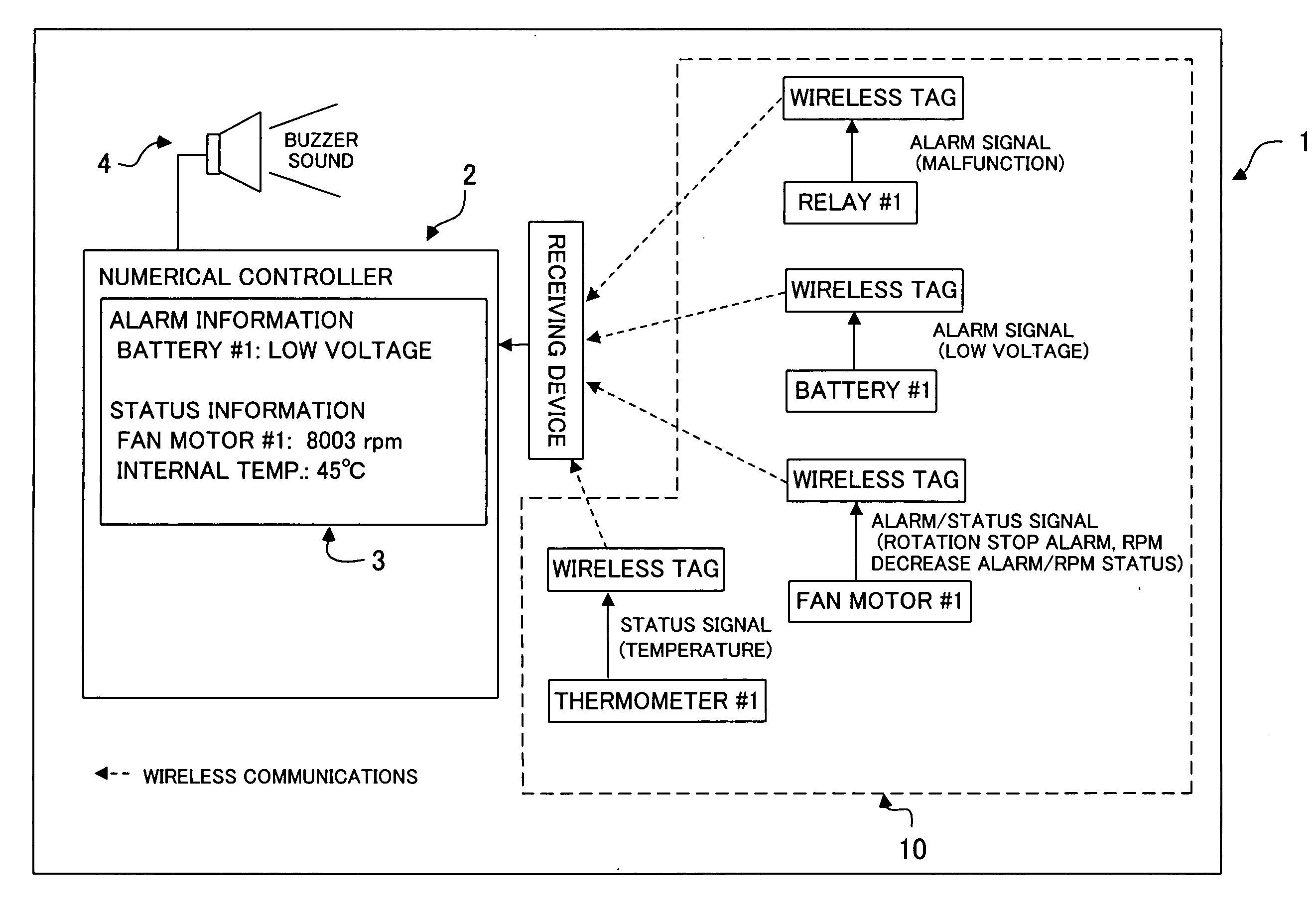
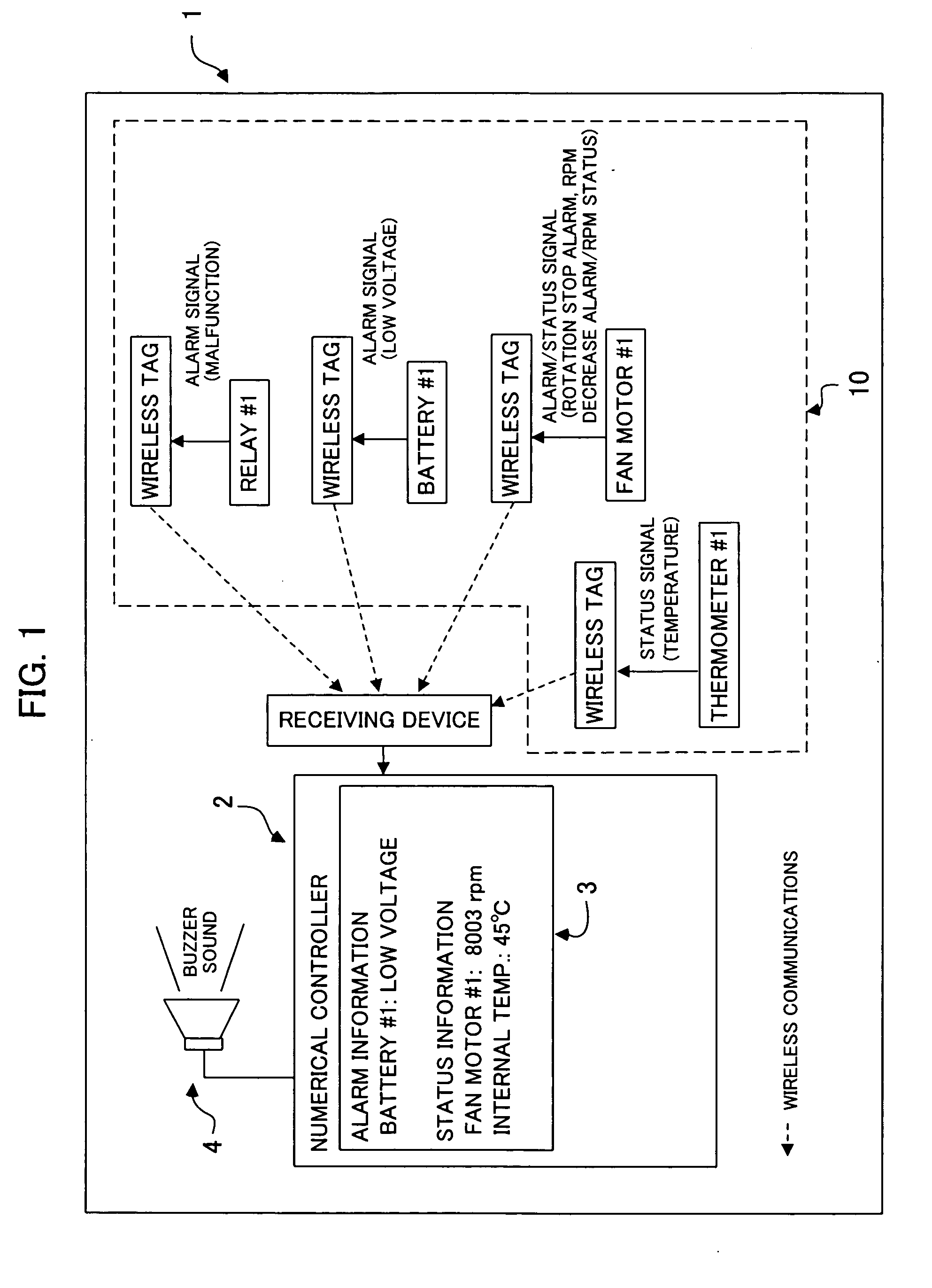
[0011]FIG. 1 is a diagram illustrating an embodiment of the present invention, showing the main parts inside a control cabinet of a machine tool. The machine tool may perform any machining process, such as cutting, punching, or the like. The entire control cabinet is indicated by reference numeral 1. A numerical controller 2 and a power managing unit 10 are contained in the control cabinet 1, and both are electrically connected in a manner that is well known. A relay that outputs a malfunction detection alarm signal, a battery that outputs a low voltage alarm signal, a fan motor that outputs an alarm signal indicating that rotation has stopped or that there is a drop in rpm as well as a status signal indicating the rpm, and a thermometer that measures ambient temperature and outputs a status signal expressing ambient temperature measurements are installed in a dispersed way in the power managing unit 10. It should be noted that the thermometer is but one example of a sensor element,...


PUM


Abstract

A numerical control unit that facilitates centralized management of alarm information from a variety of elements in a machine tool cabinet. A relay that outputs a malfunction alarm signal, a battery that outputs a low voltage alarm signal, a fan motor that outputs an alarm signal indicating rotation stop or a drop in rpm and a status signal indicating the rpm, and a thermometer or the like that outputs a status signal expressing ambient temperature measurements are installed in a power managing unit in a control unit of the machine tool. Each element is equipped with a wireless communications tag that temporarily stores the alarm signal / status signal and emits a wireless signal. The numerical control unit receives the wireless signal through a receiving device, and displays information about the cause (originating location) of the alarm and activates a buzzer (or a speaker) when an alarm occurs. Status information is displayed continuously.

Description

BACKGROUND OF THE INVENTION [0001] 1. Field of the Invention [0002] The present invention relates to a numerical control unit for a machine tool, and more particularly, to a numerical control unit that enables centralized management of alarm information from a variety of elements in a machine tool cabinet. [0003] 2. Description of Related Art [0004] As is well known, a variety of elements (also called “components”), such as a relay, a fan motor, a battery and the like, are installed in a machine tool cabinet. If a malfunction occurs in the machine tool cabinet, it is desirable to be able to centrally manage the alarm information relating to the elements in order to identify the malfunctioning element (component) promptly. However, there is no concept of centralizing management of element alarm information within the actual cabinet. In reality, such management of element alarm information is dispersed throughout the cabinet, and there is not found any publication that discloses an in...

Claims


Application Information

Patent Timeline
IPC IPC(8): G08B21/00G08B13/14G05D11/00G08B1/08
CPCG05B19/406
Inventor ANDO, HIROSHIGEKOBAYASHI, TORUNODA, HIROSHI
Owner FANUC LTD
Features
  • R&D
  • Intellectual Property
  • Life Sciences
  • Materials
  • Tech Scout
  • Unparalleled Data Quality
  • Higher Quality Content
  • 60% Fewer Hallucinations
Learn More