Piezoelectric actuator and liquid transporting apparatus

a technology of actuator and liquid, applied in piezoelectric/electrostrictive/magnetostrictive devices, instruments, printing, etc., can solve the problem of reducing the power consumption needed for driving, and achieve the effect of simplifying the manufacturing process, improving the driving efficiency of piezoelectric actuators, and facilitating deformation of vibration plates

Active Publication Date: 2006-08-17
BROTHER KOGYO KK
View PDF2 Cites 13 Cited by
  • Summary
  • Abstract
  • Description
  • Claims
  • Application Information

AI Technical Summary

Benefits of technology

[0018] In the liquid transporting apparatus of the present invention, each of the grooves may be formed to be deeper toward the edge of one of the pressure chambers. In this case, the vibration plate is thinnest at the vicinity of its portions joined to the channel unit. Accordingly, the vibration plate can be deformed more easily, thereby improving the driving efficiency of the piezoelectric actuator.
[0019] In the liquid transporting apparatus of the present invention, each of the grooves may have a cross section which is tapered to be wider toward one of the pressure chambers. In this case, the angle at the corner of each of the grooves is greater than 90 degrees. This prevents air bubbles from remaining in the corner of each groove.
[0020] In the liquid transporting apparatus of the present invention, the channel unit may have a common liquid chamber communicating with the pressure chambers; a throttle passage may be formed between the one surface of the channel unit and a portion of one of the grooves formed on the vibration plate, a sectional area of the throttle passage being partially narrowed between the common liquid chamber and one of the pressure chambers. The throttle passage, provided between the common liquid chamber and each of the pressure chambers, throttles the passage between the common liquid chamber and each of the pressure chambers so that the pressure waves generated in each of the pressure chambers is hardly propagated to the common liquid chamber. Since the sectional area of the throttle passage strongly influences the propagation of pressure waves in the pressure chamber and, as a result, the amount of transported liquid, it is necessary to form the throttle passage with precision. Here, the throttle passage is formed between the one surface of the channel unit and the portion of one of the grooves. Accordingly, the formation of the grooves in the vibration plate results in throttle passages being formed simultaneously with the formation of the grooves. This simplifies the manufacturing process and improves the manufacturing yield in comparison with a case where throttle passages, which need to be formed with precision, are formed separately from grooves by a process such as half etching.
[0021] In the liquid transporting apparatus of the present invention, the channel unit may be formed of a plurality of laminated plates in which a channel including the pressure chambers are formed; one of the plates may be formed with the pressure chambers, a plurality of through holes which are to be at least a part of channels each of which communicates the common liquid chamber and one of the pressure chambers, and partition walls each of which partitions one of the pressure chambers and one of the through holes; a surface of each of the partition walls may face the portion of one of the grooves to form the throttle passage therebetween, the surface being on a side of the vibration plate; and a side surface of each of the partition walls, the side surface facing one of the pressure chambers, may be inclined at an angle exceeding 90 degrees with respect to a surface of one of the pressure chambers facing the vibration plate. This enables liquid to be smoothly introduced from each of the throttle passages into one of the pressure chambers smoothly, and any air babbles hardly remain at the corner formed by the surface of each of the pressure chambers facing the vibration plate and the side surface of each of the partition walls. Consequently, the liquid transporting apparatus can transport liquid more stably.

Problems solved by technology

Consequently, this further reduces the power consumption necessary for driving the piezoelectric actuator.

Method used


Image

  • Piezoelectric actuator and liquid transporting apparatus
  • Piezoelectric actuator and liquid transporting apparatus
  • Piezoelectric actuator and liquid transporting apparatus

Examples


first modified embodiment

[0061] It is not necessarily indispensable that a piezoelectric layer be formed on the upper surface of the vibration plate 30 continuously over the plurality of pressure chambers 14. In a first modified embodiment, as shown in FIGS. 6 and 7, a plurality of piezoelectric layers 31A may be formed on the upper surface of the vibration plate 30 at positions each of which overlaps with one of the pressure chambers 14.

second modified embodiment

[0062] In a second modified embodiment, as shown in FIG. 8, a vibration plate 30B may be a clad material formed by laminating two metallic materials (a first metallic material layer 41 and a second metallic material layer 42) which are mutually different from each other. The second metallic material layer 42 is arranged on the channel unit 2 to cover the pressure chambers 14 which are formed through the cavity plate 10. The first metallic material layer 41 is arranged on the surface of the second metallic material layer 42. In the second metallic material layer 42, through holes 42a are formed to have a seamless circular shape. Each of the through holes 42a extends along the edge of one of the pressure chambers 14. The through holes 42a are covered with the first metallic material layer 41 so as to form grooves 40B respectively.

[0063] It is possible to form grooves 40B in the vibration plate 30B by forming the through holes 42a through the second metallic material layer 42 by subje...

third modified embodiment

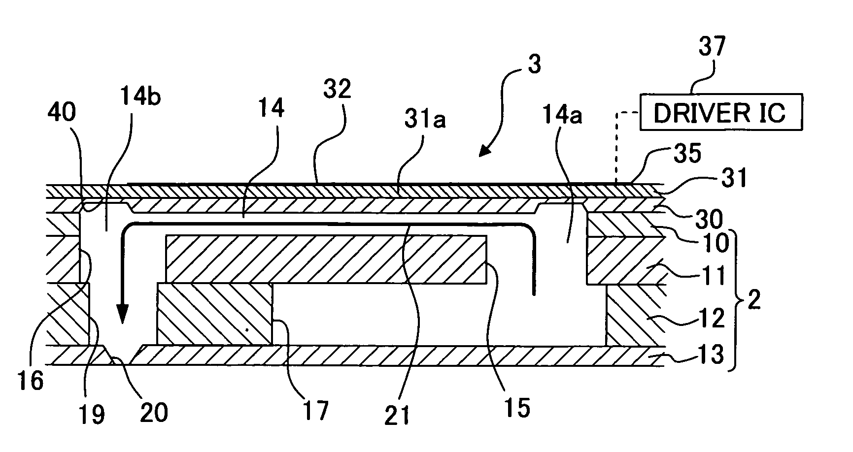
[0065] It is not necessarily indispensable that the vibration plate 30 should serve as the common electrode as is the case with the first embodiment. In a third modified embodiment, as shown in FIG. 9, a common electrode 34 may be provided separately from the vibration plate 30. When the vibration plate 30 is a metallic plate, however, the upper surface of the vibration plate 30 needs to be electrically insulative, for example, by forming an insulation material layer on the upper surface of the vibration plate 30 on which the common electrode 34 is to be formed. When the vibration plate 30 is made of silicon material, the upper surface of the vibration plate 30 may be electrically insulative by being oxidized. When the vibration plate 30 is made of an insulation material such as ceramic material or synthetic resin, the common electrode 34 is formed directly on the upper surface of the vibration plate 30.


PUM


Abstract

A piezoelectric actuator 3 of a liquid transporting apparatus includes grooves 40 which are formed on a surface of a vibration plate 30 on a side of pressure chambers 14, and each of the grooves 40 is formed at an area which is inside of the edge of one of the pressure chambers and which is outside of an area overlapping with one of individual electrodes 32. With the grooves 40, it is possible to partially reduce the rigidity of the vibration plate 30 at portions each of which surrounding one of the individual electrodes 32 (driving portions 31a), thereby improving the driving efficiency of the piezoelectric actuator 3 and to reduce the crosstalk between adjacent pressure chambers 14.

Description

FIELD OF THE INVENTION [0001] The present invention relates to a piezoelectric actuator and a liquid transporting apparatus which transports liquid by applying pressure to the liquid. BACKGROUND OF THE INVENTION [0002] A liquid transporting apparatus such as an ink-jet head, which discharges ink through its nozzles, includes a channel unit and a piezoelectric actuator. The channel unit has liquid channels formed therein. The piezoelectric actuator applies transport energy on the liquid in the channel unit. For example, FIG. 3 of Japanese Patent Application Laid-open No. 11-334087 shows an ink-jet head including a channel unit (substrate), which has a plurality of pressure chambers (pressurizing chambers) formed therein. The pressure chambers communicate with a manifold (common passage), and each of the pressure chambers communicates with a nozzle. The piezoelectric actuator is a so-called unimorph-type piezoelectric actuator, which includes a metallic vibration plate, a piezoelectri...

Claims


Application Information

Patent Timeline
Patent Type & Authority Applications(United States)
IPC IPC(8): B41J2/045
CPCB41J2/14233B41J2002/14266G02B26/0858H01L41/0973H10N30/2047
Inventor SUGAHARA, HIROTO
Owner BROTHER KOGYO KK
Why Eureka
Try Eureka