
Optical lens and semiconductor laser apparatus

a laser apparatus and optical lens technology, applied in the field of optical lenses, can solve problems such as the deterioration of outgoing light performan

Inactive Publication Date: 2006-08-17
HAMAMATSU PHOTONICS KK
View PDF25 Cites 0 Cited by
  • Summary
  • Abstract
  • Description
  • Claims
  • Application Information

AI Technical Summary

Benefits of technology

[0004] In order to overcome the problem mentioned above, it is an object of the present invention to provide an optical lens whose optically effective part is hard to damage, thus being excellent in performances of outgoing light.
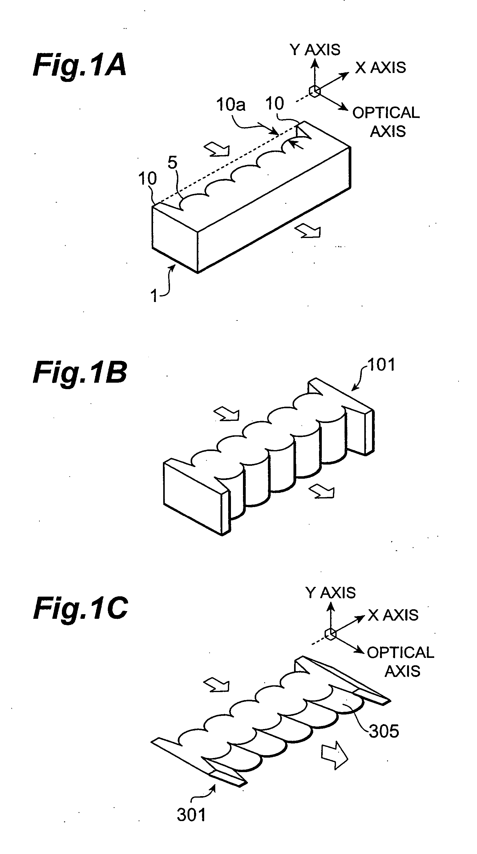
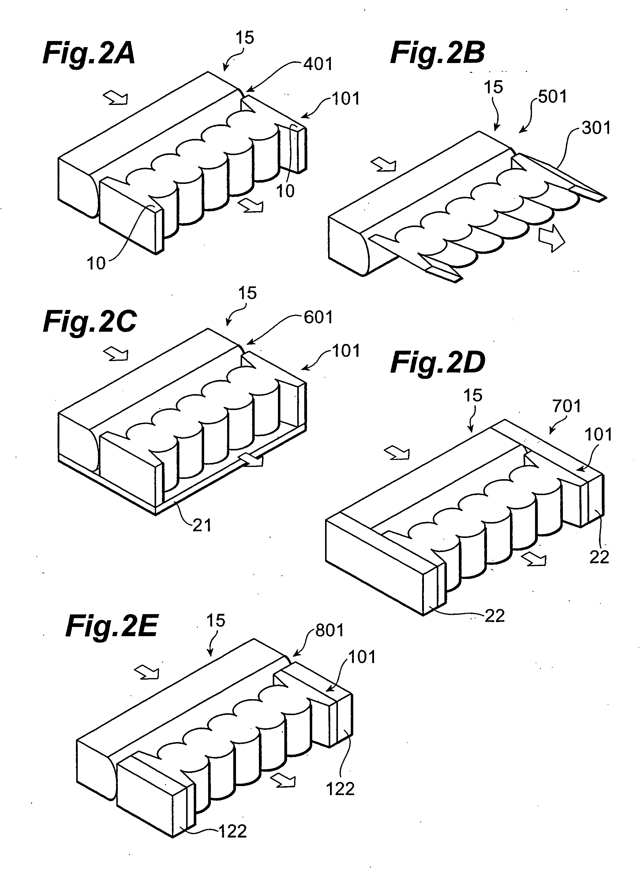
[0006] Since a pair of protrusions projecting beyond the surface of the optically effective part are formed on both sides of the light-transmitting area, such an optical lens can prevent its optically effective part from coming into direct contact with the arrangement surface where the optical lens is placed, side faces of members adjacent to the optical lens, and the like in each manufacturing step, during delivery, or the like, whereby the optically effective part is hard to incur damages and the like.
[0009] A pair of protrusions may be formed integrally in the light-entrance and light-exit faces so as to project in the optical axis direction on both sides of the light-transmitting area. This makes it possible to place separate optical lenses on both light-entrance and light-exit sides.
[0010] The optically effective part may be formed as a plurality of curved surfaces arranged in contact with each other. This makes it possible to act on individual light components emitted from a light-emitting device comprising a plurality of light-emitting parts.
[0020] As explained in the foregoing, the optical lens in accordance with the present invention is an optical lens having a pair of side faces opposing each other for receiving and emitting light; the optical lens comprising an optically effective part, provided with at least one of the pair of side faces, including a plurality of curved surfaces acting in a predetermined direction on incident light; and a pair of protrusions, formed at a side face on the side provided with the optically effective part, projecting in a direction intersecting the side face; the pair of protrusions projecting beyond a surface of the optically effective part. Therefore, the optically effective part can be prevented from coming into direct contact with an arrangement surface where the optical lens is placed, side faces of members adjacent to the optical lens, and the like, whereby the optically effective part is hard to incur damages and the like.

Problems solved by technology

Such a conventional type optical lens has been problematic in that the optically effective part may be damaged upon coming into contact with the arrangement surface where the optical lens is placed or other members, thus deteriorating performances of outgoing light.

Method used


Image

  • Optical lens and semiconductor laser apparatus
  • Optical lens and semiconductor laser apparatus
  • Optical lens and semiconductor laser apparatus

Examples


Embodiment Construction

[0027] In the following, optical lenses and semiconductor laser apparatus in accordance with embodiments of the present invention will be explained in detail with reference to the drawings. In the following explanation, parts identical or equivalent to each other will be referred to with numerals identical to each other without repeating their overlapping descriptions.

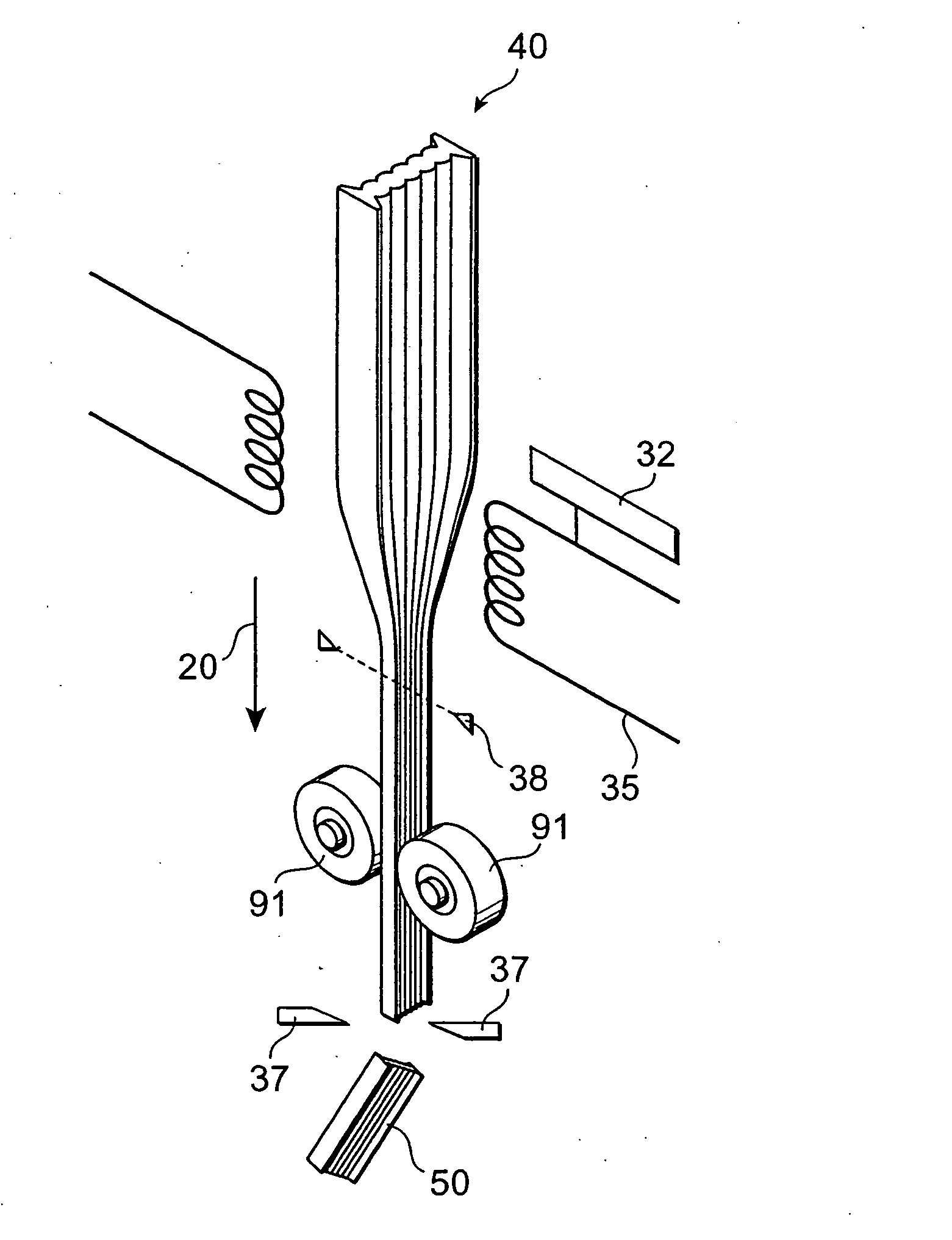
[0028]FIGS. 1A to 1C and 2A to 2E are overall views of optical lenses in accordance with embodiments, respectively. In these embodiments, the X-axis direction, Y-axis direction, and optical axis direction in the drawings are assumed to be orthogonal to each other. In the optical lens 1 shown in FIG. 1A, respective light components emitted from light-emitting parts of a semiconductor laser device (not depicted) acting as a light-emitting device are collimated in the X-axis direction by an optically effective part 5, and thus collimated light is emitted therefrom. The optically effective part 5 is formed as a convex sur...


PUM


Abstract

The optical lens 1 in accordance with the present invention comprises an optically effective part 5, formed as a curved surface in at least one of light-entrance and light-exit faces, for acting in an X-axis direction on light emitted from a light-emitting device; and a pair of protrusions 10, integrally formed in the face on the side provided with the optically effective part 5, projecting in an optical axis direction on both sides of a light-transmitting area; the pair of protrusions 10 projecting beyond a surface of the optically effective part. Such an optical lens 1 can prevent the optically effective part 5 from coming into direct contact with an arrangement surface where the optical lens 1 is placed, side faces of members adjacent to the optical lens 1, and the like in each manufacturing step, during delivery, and so forth, whereby the optically effective part 5 is hard to incur damages and the like.

Description

TECHNICAL FIELD [0001] The present invention relates to an optical lens acting on light emitted from a light-emitting device. BACKGROUND ART [0002] In a conventional type optical lens, there has been a case where an optically effective part, which is a part collimating or converging incident light, comes into contact with an arrangement surface where the optical lens is placed, side faces of members adjacent to the lens, and the like in each manufacturing step or during delivery. DISCLOSURE OF THE INVENTION [0003] Such a conventional type optical lens has been problematic in that the optically effective part may be damaged upon coming into contact with the arrangement surface where the optical lens is placed or other members, thus deteriorating performances of outgoing light. [0004] In order to overcome the problem mentioned above, it is an object of the present invention to provide an optical lens whose optically effective part is hard to damage, thus being excellent in performance...

Claims


Application Information

Patent Timeline
Patent Type & Authority Applications(United States)
IPC IPC(8): G02B27/10G02B3/00G02B27/09H01S5/00H01S5/40
CPCG02B3/0012G02B3/005G02B3/0068G02B3/0075G02B27/09G02B27/0905G02B27/0961G02B27/0966G02B27/0977H01S5/005H01S5/4025G02B19/0052G02B19/0014H01S3/10
Inventor KUSUYAMA, YUTAKA
Owner HAMAMATSU PHOTONICS KK
Learn More