LED light module assembly

a technology of led light and assembly, which is applied in the direction of semiconductor devices for light sources, light and heating apparatus, printed element electric connection formation, etc., can solve the problems of increasing the power density and operating temperature of these devices, and increasing the cost of assembly

Active Publication Date: 2006-08-17
FEDERAL MOGUL WORLD WIDE LLC
View PDF7 Cites 139 Cited by
  • Summary
  • Abstract
  • Description
  • Claims
  • Application Information

AI Technical Summary

Problems solved by technology

While significant advances have been made in improving the light output and reducing the size of LED's, their commercialization has been somewhat limited in part by difficulties associated with the removal of the increased amounts of heat generated by these higher power devices using existing electronics packaging technology and lighting module designs.
In addition to the increased power consumption of the LED's, there is also a desire to increase the packaging density of the LED's on the circuit boards into ever denser arrays and other configurations, which correspond to higher light outputs per unit area, but also increase the power densities and operating temperatures of these devices, and further compounds the problems associated with thermal management of lighting modules which incorporate them and maintaining the necessary operating limits, such as Tj.
However, increases in packaging density have been limited by the thermal management issues described above.
In addition to the limitations associated with packaging high power, high density LED's described above, the current state-of-the-art of electronic packaging technology for LED's used in lighting module applications is not particularly well adapted for handling and assembly using high volume assembly methods.
For example, surface mounting with reflow soldering of the LED's on the circuit boards using standard techniques is either currently not feasible and / or extremely difficult with many of these newly released LED high power packages.
Additionally, high volume automation and integration of the aforementioned thermal pathways and / or heat sinks into, through, and around the LED lighting modules have not been demonstrated in large scale to date.

Method used


Image

  • LED light module assembly
  • LED light module assembly
  • LED light module assembly

Examples


Embodiment Construction

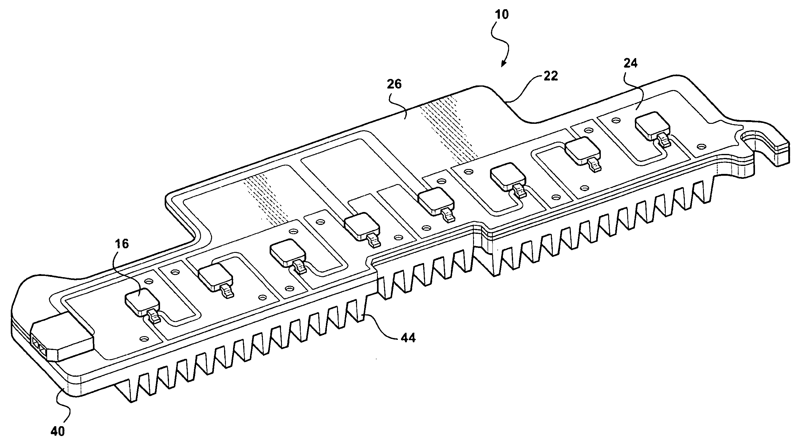
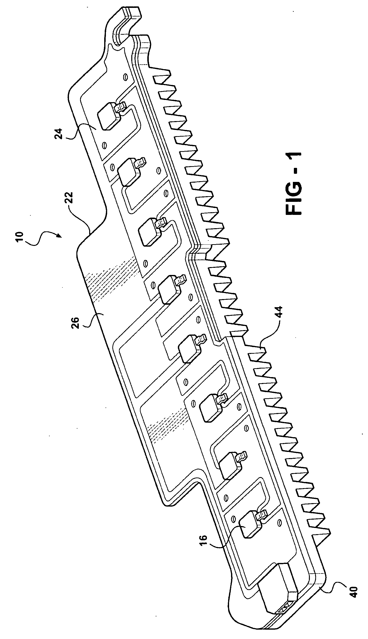
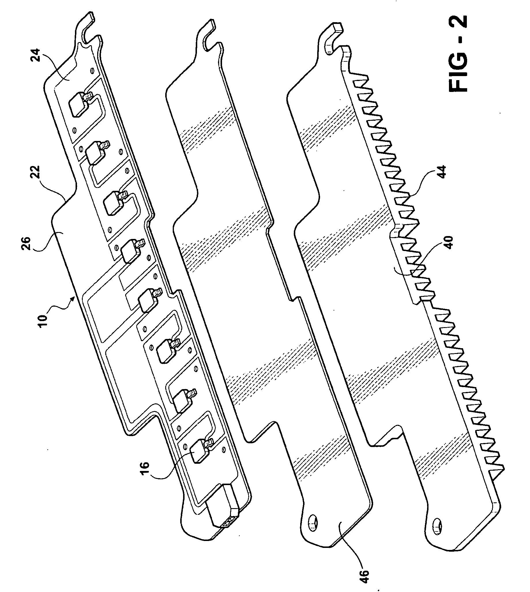
[0030] Referring to FIGS. 1-11, this invention is an LED lighting module assembly 10 for use in many lighting applications, including automotive lighting applications. The LED lighting module assembly 10 includes at least one LED 12 that is operatively connected to a first surface 14 of an LED carrier 16 (FIGS. 1 and 8). The LED carrier 16 also has a carrier metallization layer 18 on a second surface 20. The LED lighting module assembly 10 also includes a flexible circuit board 22 which includes a first metallization layer 24, a dielectric layer 26 and a second metallization layer 28. The dielectric layer 26 is located between the first metallization layer 24 and the second metallization layer 28. The first metallization layer 24 has at least one LED attachment pad 30 defined on it. The attachment pad 30 has at least one via 32 or opening which extends through the dielectric layer 26 from the first metallization layer 24 to the second metallization layer 28. The via 32 has around it...


PUM


Abstract

An LED light module assembly for use with high power, high light output LED's includes a thin flexible circuit board with surface mounted LED's and other electronic components which is attached to a metal heat sink using a layer of a thermally conductive adhesive, such as a thermally conductive epoxy adhesive. A conduction path is provided from the LED carrier through the flexible circuit board by the incorporation of one or more thermally conductive vias in the region of the attachment pad used to bond the LED to the flexible circuit board. These vias provide a conduction path from the back side of the LED carrier through the circuit board to the thermally conductive adhesive and heat sink. The LED light module assembly has the capacity to dissipate between about 10-14 W of power without exceeding a maximum LED junction temperature of about 125° C.

Description

CROSS-REFERENCES TO RELATED APPLICATIONS [0001] This patent application claims priority to U.S. Provisional Patent Application Ser. No. 60 / 654,027, filed Feb. 17, 2005 which is incorporated herein by reference in its entirety.BACKGROUND OF THE INVENTION [0002] 1. Technical Field [0003] This invention relates generally to lighting assemblies. More particularly, it relates to LED light module assemblies. Most particularly, it relates to LED light module assemblies for high-power LED arrays having controlled thermal pathways and heat sinks to remove the heat generated by operation of the LED's and associated electronics. [0004] 2. Related Art [0005] Lighting modules which utilize light emitting diodes (LED) as light sources are used currently in a wide variety of lighting applications, including automotive applications. Because of their ability to provide a relatively high light output per unit area and their ability to be flexibly arranged into modular light arrays of various configur...

Claims


Application Information

Patent Timeline
Patent Type & Authority Applications(United States)
IPC IPC(8): F21V29/00F21K99/00H01L33/48H01L33/32H01L33/64
CPCF21K9/00F21V29/763F21S48/328F21V29/004F21Y2101/02H05K1/0206H05K1/189H05K3/0061H05K3/42H05K2201/10106H05K2201/10651Y10S362/80F21S48/211F21S48/215F21V29/74F21V29/75F21S48/321F21K9/20F21Y2115/10F21S43/19F21S43/14F21S45/49F21S45/48
Inventor BURKHOLDER, GREG EUGENE
Owner FEDERAL MOGUL WORLD WIDE LLC
Why Eureka
Try Eureka