Audio quality adjustment device

a tone control and audio quality technology, applied in the direction of untuned amplifier combination control, transducer casing/cabinet/support, electrical transducer, etc., can solve the problem of not having a desired filter characteristic, large amount of arithmetic operation of the filter, and low degree of flexibility, so as to achieve high-precision tone control and suppress ripple

Inactive Publication Date: 2006-08-17
MITSUBISHI ELECTRIC CORP
View PDF4 Cites 27 Cited by
  • Summary
  • Abstract
  • Description
  • Claims
  • Application Information

AI Technical Summary

Benefits of technology

[0013] As a result, the tone control apparatus can suppress occurrence of ripples in the tone control filter and can provide high-precision tone control.

Problems solved by technology

However, an FIR filter generally has a large amount of arithmetic operation and a large delay time, as compared with an IIR filter.
While a typical IIR filter has a low degree of flexibility, it cannot necessarily have a desired filter characteristic.
Furthermore, the LMA filter has a relatively small amount of arithmetic operation required for calculation of a filter factor thereof and filtering processing.
However, in a case of an IIR filteror an LMA filter having a filter factor which is an LPC coefficient to which a cepstrum as mentioned above is converted, a ripple which is contrary to a desired filter response may occur in the response characteristic of the filter which is actually formed.
Particularly, when a steep characteristic change point, such as a sharp peak or dip, exists in the desired filter response, such a ripple appears notably and becomes a factor to reduce the accuracy of the tone control apparatus.
On the other hand, when there is a limit on the hardware scale or the amount of arithmetic operation of the filter, it is difficult to increase the length of quefrency for the cepstrum.

Method used


Image

  • Audio quality adjustment device
  • Audio quality adjustment device
  • Audio quality adjustment device

Examples


embodiment 1

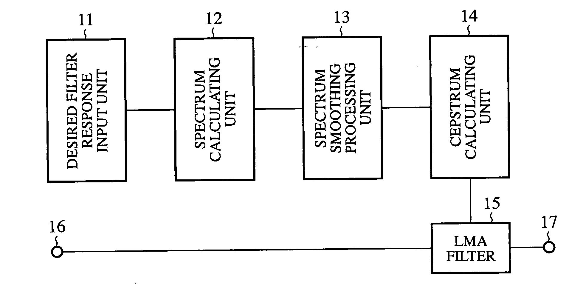
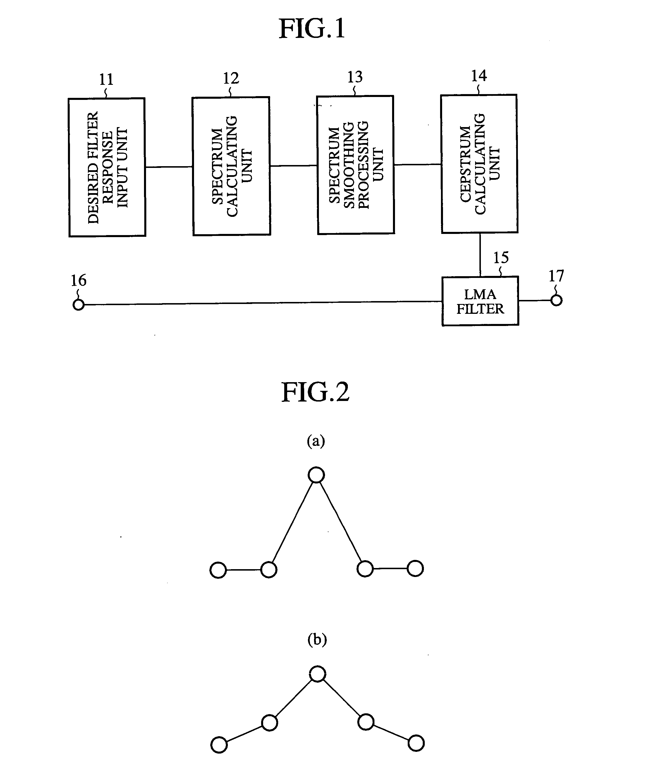
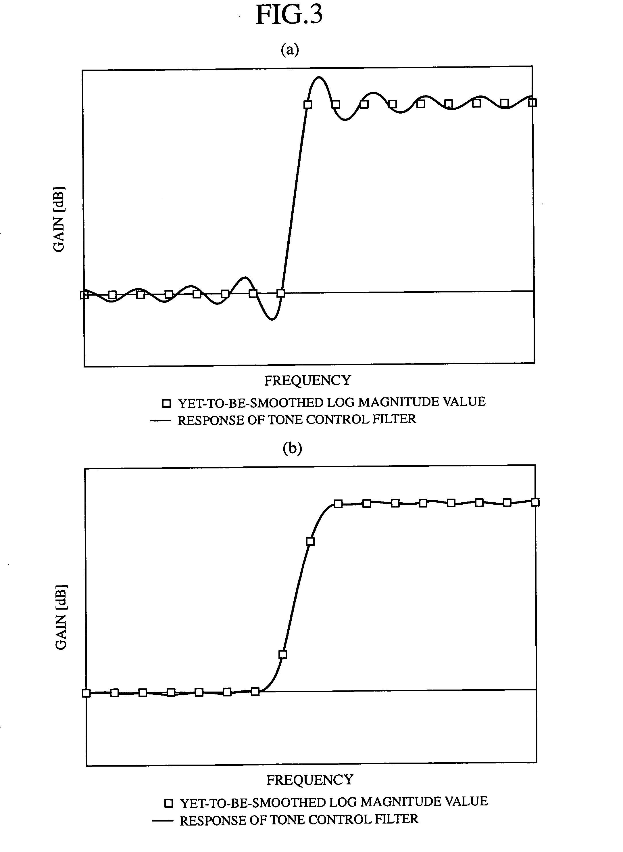
[0024] A tone control apparatus in accordance with embodiment 1 of the present invention will be explained hereafter with reference to FIGS. 1 to 3. FIG. 1 is a block diagram showing the structure of the tone control apparatus in accordance with embodiment 1, FIG. 2 is a diagram for explaining a smoothing method of smoothing a Fourier spectrum, which this tone control apparatus uses, and FIG. 3 is a diagram for explaining an advantage provided by the smoothing method of smoothing a Fourier spectrum which the tone control apparatus uses.

[0025] This embodiment 1 is an example in which a desired filter response to the tone control apparatus is predetermined, and a filter factor of the tone control filter is calculated for the desired filter response. Assume that an LMA filter is used as the tone control filter in this embodiment.

[0026] As shown in FIG. 1, the tone control apparatus in accordance with embodiment 1 is provided with a desired filter response input unit 11 for inputting ...

embodiment 2

[0043] A tone control apparatus in accordance with embodiment 2 of the present invention will be explained hereafter with reference to FIG. 4. FIG. 4 is a diagram for explaining a smoothing method of smoothing a spectrum which the tone control apparatus in accordance with embodiment 2 uses.

[0044] Instead of the median filter with a low pass characteristic, which is disposed as the spectrum smoothing method in accordance with above-mentioned embodiment 1, the tone control apparatus in accordance with this embodiment 2 uses a method of replacing each odd or even-numbered sampled value of spectrum data as shown in FIG. 4 with an average of two sampled values adjacent to each odd or even-numbered sampled value. The other components and these components' workings of the tone control apparatus in accordance with embodiment 2 are the same as those explained in embodiment 1, and therefore the explanation of the other components and these components workings will be omitted hereafter.

[0045...

embodiment 3

[0048] A tone control apparatus in accordance with embodiment 3 of the present invention will be explained hereafter with reference to FIGS. 5 and 6. FIG. 5 is a diagram for explaining a spectrum smoothing method which the tone control apparatus in accordance with embodiment 3 of the present invention uses, and FIG. 6 is a flowchart for explaining the spectrum smoothing method which the tone control apparatus in accordance with embodiment 3 of the present invention uses.

[0049] Although the tone control apparatus in accordance with either of above-mentioned embodiments 1 and 2 performs the smoothing processing on a Fourier spectrum of a desired filter response over an entire frequency range, a ripple which occurs in the tone control filter substantially results from a steep change in the filter characteristic of the tone control filter, such as a peak and a dip which appears in the Fourier spectrum. Therefore, the tone control apparatus in accordance with this embodiment 3 does not ...


PUM


Abstract

A tone control apparatus is provided with a desired filter response input unit 11 for inputting a desired filter response into the tone control apparatus, a spectrum calculating unit 12 for calculating a Fourier spectrum for the set filter response which is inputted by the desired filter response input unit 11, a spectrum smoothing processing unit 13 for performing smoothing processing on the Fourier spectrum calculated by the spectrum calculating unit 12, a cepstrum calculating unit 14 for converting the Fourier spectrum smoothed by spectrum smoothing processing unit 13 into a cepstrum, and an LMA filter 15 to which the cepstrum calculated by the cepstrum calculating unit 14 is set as the filter factor of the LMA filter. The tone control apparatus also has an input terminal 16 for inputting a sound signal into the LMA filter 15, and an output terminal 17 for outputting a sound signal.

Description

FIELD OF THE INVENTION [0001] The present invention relates to a tone control apparatus provided with a digital filter. BACKGROUND OF THE INVENTION [0002] There is a method of using a digital filter as a method of adjusting the tone quality of a sound signal. Either of an FIR (Finite Impulse Response) filter and an IIR (Infinite Impulse Response) filter is used as such a digital filter which constitutes a tone control filter. [0003] It is necessary to design a desired filter response using a certain method when designing a tone control filter. For example, there are methods of representing the desired filter response as a Fourier spectrum, and computing a filter factor based on the Fourier spectrum. According to an example of such related art methods, an impulse response is obtained by carrying out an inverse Fourier transform of the Fourier spectrum, and the impulse response is then set as the filter factor of the tone control filter. According to this method, the filter factor can...

Claims


Application Information

Patent Timeline
Patent Type & Authority Applications(United States)
IPC IPC(8): H03G5/00H03G5/06H03G5/02H03H17/00H03H17/02H03H17/04
CPCH03H17/0213
Inventor YANO, ATSUYOSHI
Owner MITSUBISHI ELECTRIC CORP
Why Eureka
Try Eureka