Syringe safety device

a safety device and syringe technology, applied in the field of syringe safety devices, can solve the problems of medication leakage from the syringe orifice, significant amount of pressure or vacuum may be created in the vial, and the medication typically has a longer shelf life than medications

Inactive Publication Date: 2006-08-17
WEST PHARM SERVICES INC
View PDF99 Cites 137 Cited by
  • Summary
  • Abstract
  • Description
  • Claims
  • Application Information

AI Technical Summary

Benefits of technology

[0011] In another aspect, the present invention is directed to a syringe safety device configured to form a fluid coupling between a sealed vial and a syringe. The syringe safety device includes a connector for receiving the sealed vial and syringe at opposite ends thereof. The connector defines a connector axis and a sliding linkage is movably mountable on the connector axis within the connector. A needle is mounted to a first side of the sliding linkage on the connector axis and a spike is mounted to a second side of the sliding linkage on the connector axis. The spike or the needle includes a first luer lock connector that releasably mounts to a second luer lock connector of the sliding linkage.
[0012] In another aspect, the present invention is directed to a syringe safety device configured to form a fluid coupling between a vial and a syringe. The syringe safety device includes a connector having a syringe end and a vial end. The connector defines a connector axis and the syringe is removably mountable to the syringe end. The via...

Problems solved by technology

Powdered medications typically have a longer shelf life than medications provided in a mixed or liquid solution form.
In addition, the medication may leak from the syringe orifice.
Further, when transferring a relatively large volume of flu...

Method used


Image

  • Syringe safety device
  • Syringe safety device
  • Syringe safety device

Examples


Embodiment Construction

[0032] Certain terminology is used in the following description for convenience only and is not limiting. The words “right”, “left”, “lower” and “upper” designate directions in the drawings to which reference is made. The words “inwardly” and “outwardly” refer to directions toward and away from, respectively, the geometric center of the syringe safety device and designated parts thereof. The terminology includes the above-listed words, derivatives thereof and words of similar import.

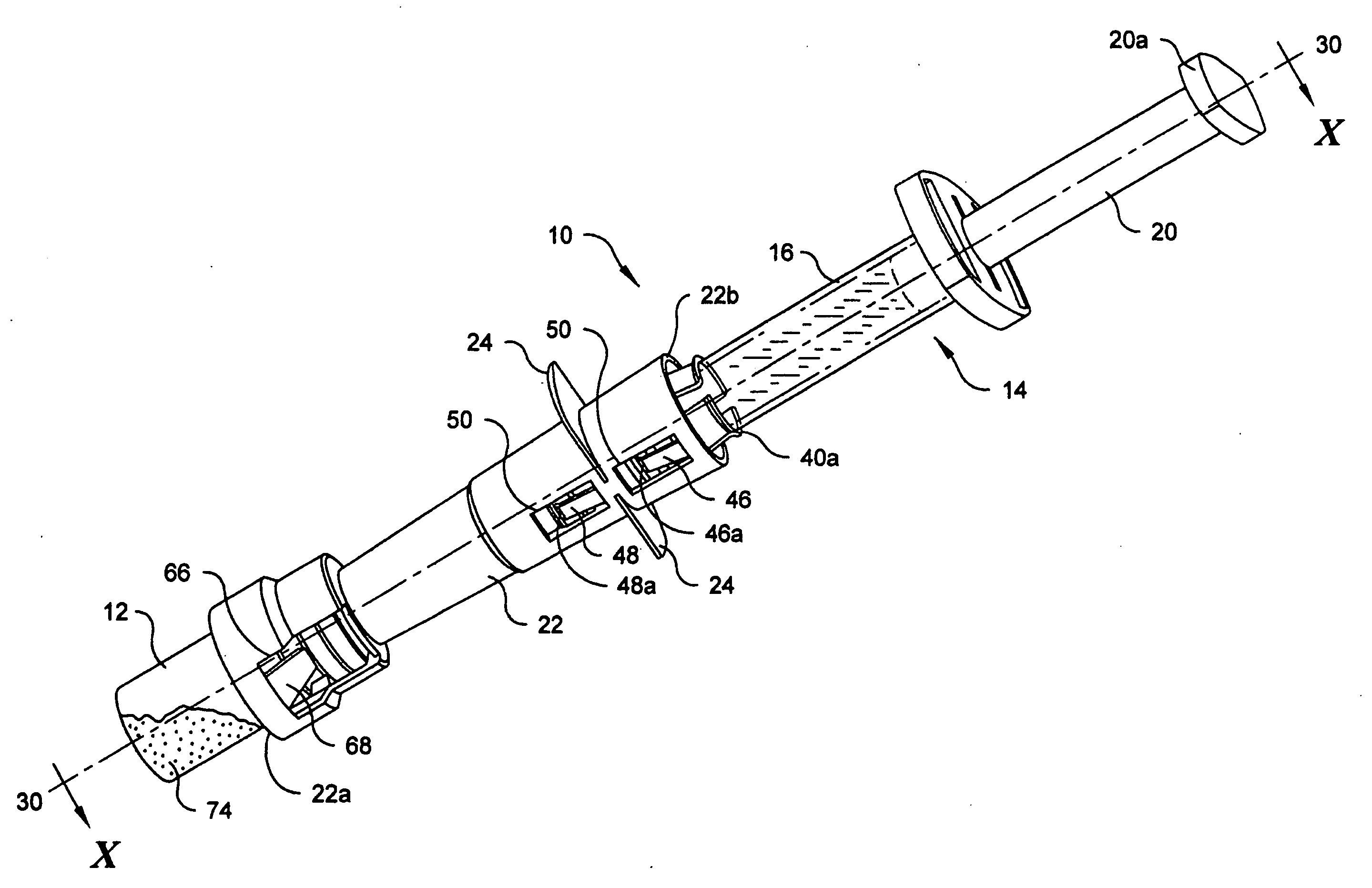
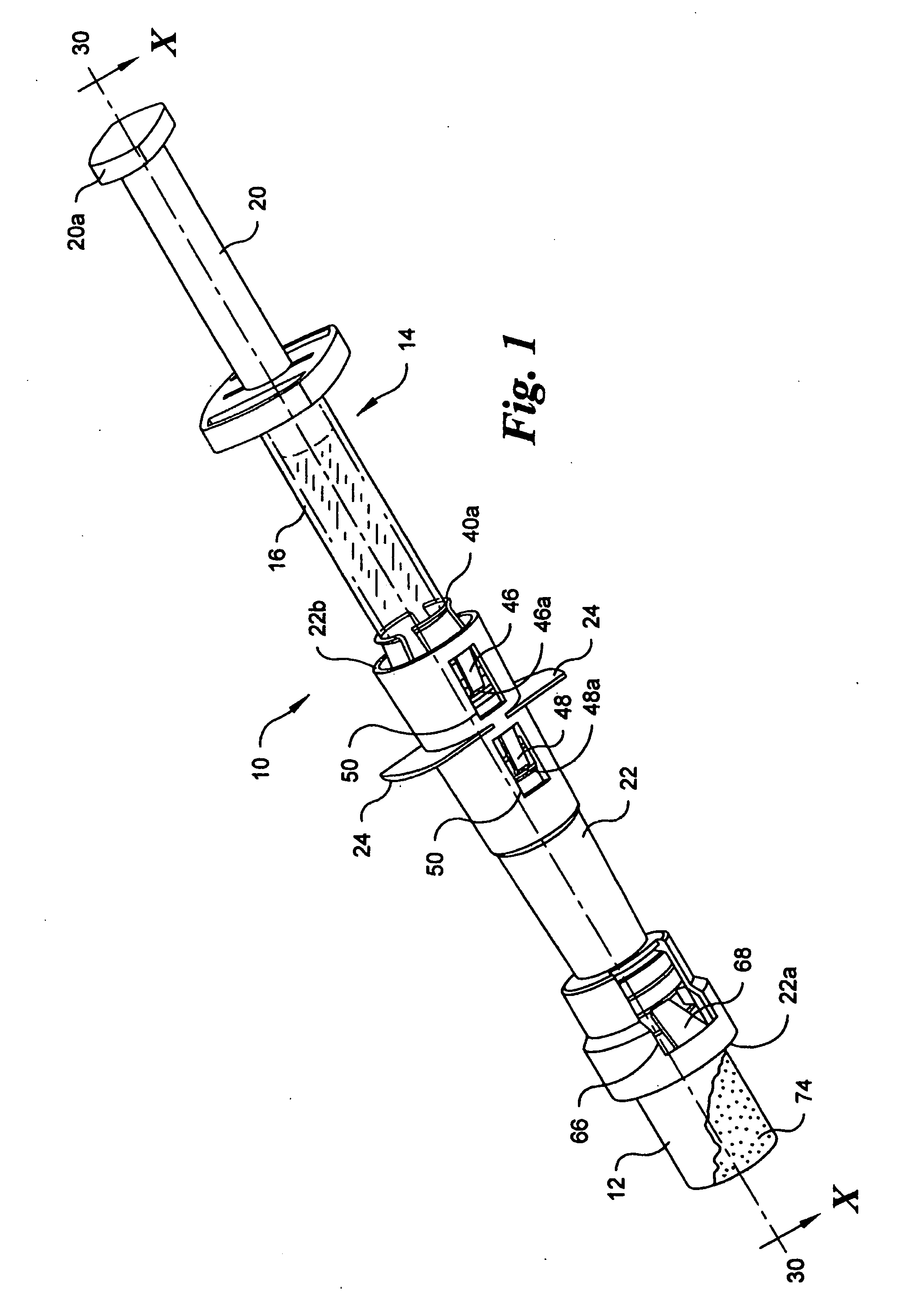
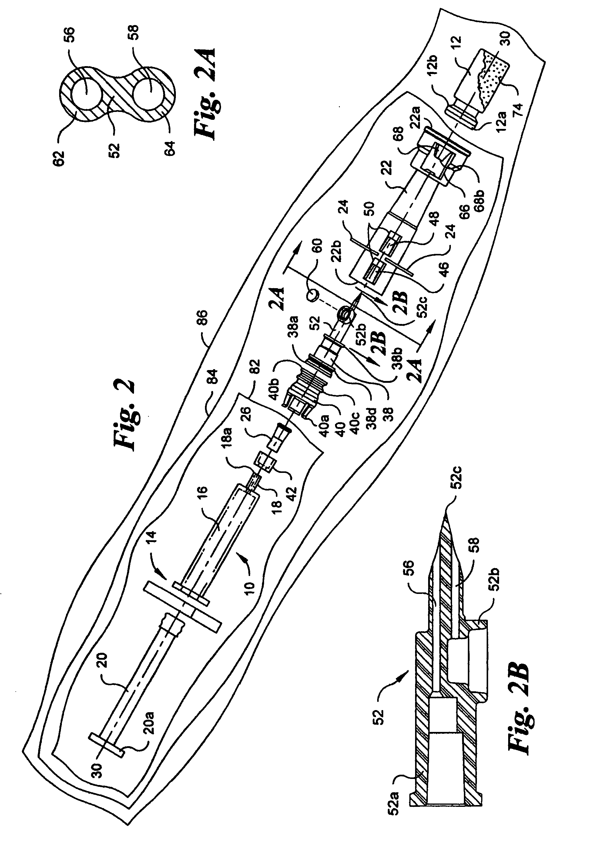
[0033] Referring to the drawings in detail, wherein like numerals indicate like elements throughout, there is shown in FIGS. 1-8 a first preferred embodiment of a syringe safety device, generally designated 10, configured to form a fluid coupling between a sealed vial 12 and a syringe 14. The syringe 14 includes a barrel 16 for receiving fluid and a luer cone 18 extending from the barrel 16 for dispensing or receiving fluid. The luer cone 18 has a distal end 18a with a syringe orifice 18b therethrough. ...


PUM


Abstract

A syringe safety device configured to form a fluid coupling between a sealed vial and a syringe having a barrel for receiving fluid and a luer cone extending from the barrel for dispensing the fluid therethrough. The luer cone has a distal end with a syringe orifice therethrough. A connector includes a vial end and a syringe end. The syringe is removably mountable to the syringe end and the vial is mountable to the vial end. A tip cap is removably mounted to the luer cone of the syringe. The tip cap and the distal end define an open receiving space therebetween. A needle is removably mounted to the connector. The needle includes a needle tip facing toward the syringe in an assembled configuration. The needle tip is positioned in the receiving space when the connector and syringe are positioned in an engaged position.

Description

BACKGROUND OF THE INVENTION [0001] The present application is directed to a syringe safety device for forming a fluid coupling between a sealed vial and a syringe. The syringe safety device preferably limits the exposure of a sharp needle to a user and, therefore, inadvertent pricks from the needle. The syringe safety device also provides a relatively simple process for mixing a diluent and a powdered medication to produce an injectable medication solution. It is often desirable to store drugs in a powdered form until immediately prior to administering the drug to a patient. Powdered medications typically have a longer shelf life than medications provided in a mixed or liquid solution form. Accordingly, powdered medications may be stored for a longer period of time and mixed with the diluent prior to use such that the shelf life of the medication is prolonged. [0002] Several apparatus for transferring fluids between a vial and a syringe that generally protect a user from needle pric...

Claims


Application Information

Patent Timeline
IPC IPC(8): A61M37/00A61B19/00A61M5/32
CPCA61J1/2096A61J2001/2013A61J2001/2017A61J2001/2051A61J2001/2055A61J2001/2075A61J2001/2082A61J2001/2086A61J1/2017A61J1/2055A61J1/2075A61J1/2086A61J1/2051A61J1/2082A61J1/2013A61J1/201A61M2005/3104
Inventor PAPROSKI, JOHNNORTON, PAUL
Owner WEST PHARM SERVICES INC
Why Eureka
Try Eureka