Medicine infuser for displaying image of entered infusion condition

a technology of infuser and display data, which is applied in the field of liquid injector, can solve the problems of inability to provide optimal imaging conditions in imaging diagnostic apparatus combined therewith, difficulty for the operator to intuitively understand the injection condition from the displayed data, etc., and achieves the effect of simple and easy input actions

Active Publication Date: 2006-08-17
NEMOTO KYORINDO KK
View PDF6 Cites 40 Cited by
  • Summary
  • Abstract
  • Description
  • Claims
  • Application Information

AI Technical Summary

Benefits of technology

[0018] The present invention has been made in view of the abovementioned problems, and it is an object of the present invention to provide a liquid injector which allows simple and easy input actions of an injection condition, instinctive understanding of the injection condition, and quick check of the numerical values.
[0022] In the liquid injector of the first aspect of the present invention, it is. only necessary for the operator to enter the injection time period and the injection rate as the injection condition, so that the input action is simple and easy. Since the condition image having the horizontal width corresponding to the injection time period and including the injection rate as text data is displayed in the condition screen with its vertical axis representing the injection rate and its horizontal axis representing the injection time period at the vertical position in association with the injection rate and the horizontal position in association with the injection time period, the operator easily understands instinctively the injection condition from the horizontal width and the position of the condition image. In addition, the injection rate is included as text data in the condition image, so that the operator can quickly check the numerical values thereof.
[0025] In the liquid injector of the second aspect of the present invention, it is only necessary for the operator to enter the injection quantity and the injection rate as the injection condition, so that the input action is simple and easy. Since the condition image having the horizontal width corresponding to the injection quantity and including the injection rate as text data is displayed in the condition screen with its vertical axis representing the injection rate and its horizontal axis representing the injection quantity at the vertical position in association with the injection rate and the horizontal position in association with the injection quantity, the operator easily understands instinctively the injection condition from the horizontal width and the position of the condition image. In addition, the injection rate is included as text data in the condition image, so that the operator can quickly check the numerical values thereof.

Problems solved by technology

Therefore, the conventional liquid injector which injects a contrast media at a constant rate that is represented by entered numerical data fails to provide optimum-imaging conditions in an imaging diagnostic apparatus combined therewith.
However, in the liquid injector described above, when the operator enters numerical data representing injection condition such as the injection rate with a numeric keypad, the entered numerical data is only displayed as text data, and thus it is difficult for the operator to understand intuitively the injection condition from that displayed data.
Therefore, the operation is complicated and is not easy for an unskilled operator, and entry of inappropriate numerical values cannot be prevented.
However, such detailed entries and control may not be required in the actual medical environment, and simpler input actions and displays may be desired.
In addition, the operator can easily understand instinctively the injection condition as described above, but the numerical values of the injection condition is difficult to review quickly.

Method used


Image

  • Medicine infuser for displaying image of entered infusion condition
  • Medicine infuser for displaying image of entered infusion condition
  • Medicine infuser for displaying image of entered infusion condition

Examples


Embodiment Construction

[Configuration of the Embodiment]

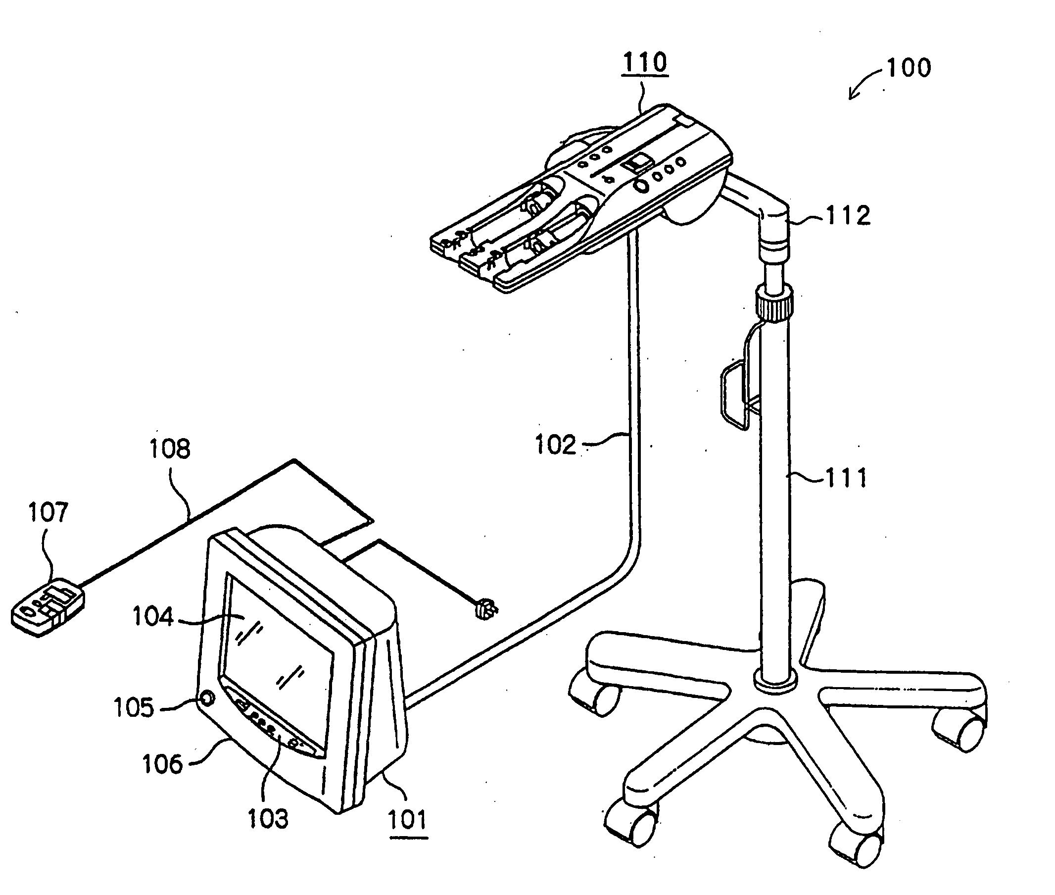
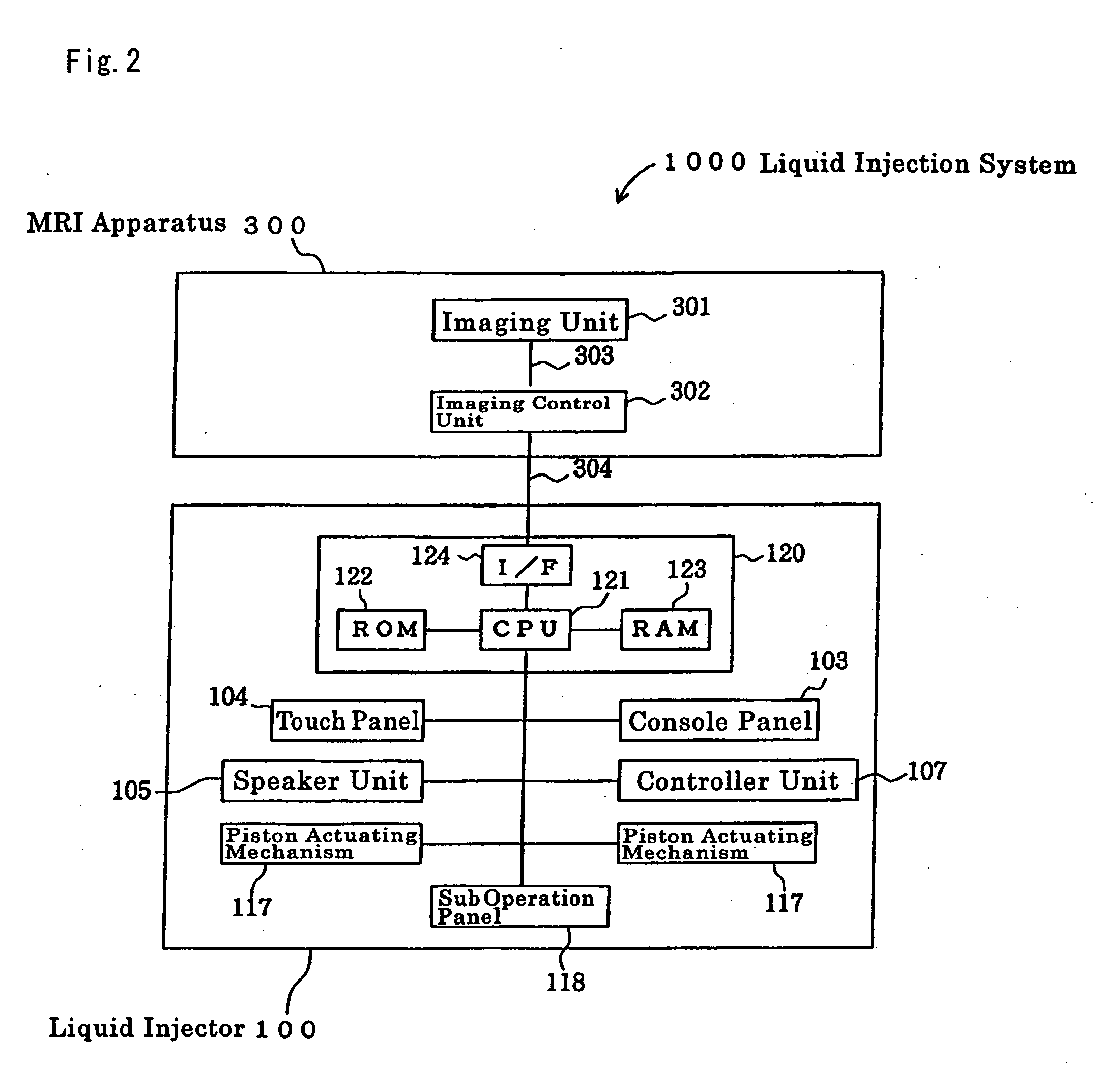
[0044] Explanation is presented below regarding an embodiment of the present invention referring to drawings. The liquid injection system 1000 of an embodiment according to the present invention, comprises liquid injector 100, liquid syringe 200 and MRI apparatus 300, which is a diagnostic imaging apparatus, as shown in FIG. 1 to FIG. 4. The system is intended for injecting a contrast media or the like as a liquid to a patient (not shown) as will be described in detail later.

[0045] The MRI apparatus 300 is provided with diagnostic imaging unit 301, which is an installation for implementing imaging, and imaging control unit 302, as shown in FIG. 3, with diagnostic imaging unit 301 and imaging control unit 302 wired-connected through communication network 303. Diagnostic imaging unit 301 shoots a diagnostic image of a patient, and imaging control unit 302 controls the operation of diagnostic imaging unit 301.

[0046] Liquid syringe 200 comprises cylin...


PUM


Abstract

The preset invention provides a liquid injector in which, when an injection time period and an injection rate are entered as an injection condition, a condition image having a horizontal width corresponding to the injection time period and including the injection rate as text data is displayed in a condition screen with its vertical axis representing the injection rate and its horizontal axis representing the injection time period at a vertical position in association with the injection rate and a horizontal position in association with the injection time period. The operator easily understands instinctively the injection condition from the horizontal width and the position of the condition image, and since the condition image includes the injection rate as text data, the operator can check quickly the numerical values. Thus, the liquid injector can be provided which allows simple entry and review of the injection condition.

Description

TECHNICAL FIELD [0001] The present invention relates to a liquid injector for injecting a liquid into a patient, and more particularly to a liquid injector for injecting a liquid, such as a contrast media, into a patient who is to be imaged by an imaging diagnostic apparatus such as a CT (Computed Tomography) apparatus, an MRI (Magnetic Resonance Imaging) apparatus, a PET (Positron Emission Tomography) apparatus, or the like. BACKGROUND ART [0002] Presently available imaging diagnostic apparatus for capturing fluoroscopic images of patients include CT scanners, MRI apparatus, PET apparatus, ultrasonic diagnostic apparatus, CT angiography apparatus, MR angiography apparatus, and ultrasonograph. When such an imaging diagnostic apparatus is used to capture a fluoroscopic image of a patient, it is occasionally practiced to inject a liquid such as a contrast media or a physiological saline into the patient. A liquid injector for automatically injecting a liquid into a patient has been co...

Claims


Application Information

Patent Timeline
Patent Type & Authority Applications(United States)
IPC IPC(8): A61M37/00A61M5/00A61M5/14A61M5/145A61M5/168
CPCA61M5/007A61M5/1408A61M5/14546A61M5/1456A61M5/16827A61M2205/583
Inventor NEMOTO, SHIGERU
Owner NEMOTO KYORINDO KK
Why Eureka
Try Eureka