Controller

Inactive Publication Date: 2006-08-17
FANUC LTD
View PDF15 Cites 11 Cited by
  • Summary
  • Abstract
  • Description
  • Claims
  • Application Information

AI Technical Summary

Benefits of technology

[0022] Abnormality can be accurately detected, since vibration or the like of the driven element is detected based on the detected acceleration value detected by the acceleration detecting means that is attached to the driven element or the like. Further, vibration or the like of necessary regions can be dete

Problems solved by technology

In the case of a machine tool, its machining accuracy lowers.
It is difficult, however, to detect these prolonged changes.
If the velocities and accelerations of the driven elements change suddenly, moreover, the driven elements may be caused to vibrate in some cases.
It is hard to detect swing of a machine or reduction in machine strength that is cau

Method used


Image

  • Controller
  • Controller
  • Controller

Examples


first embodiment

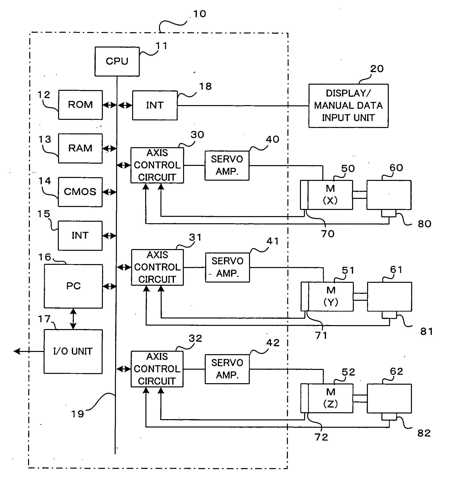
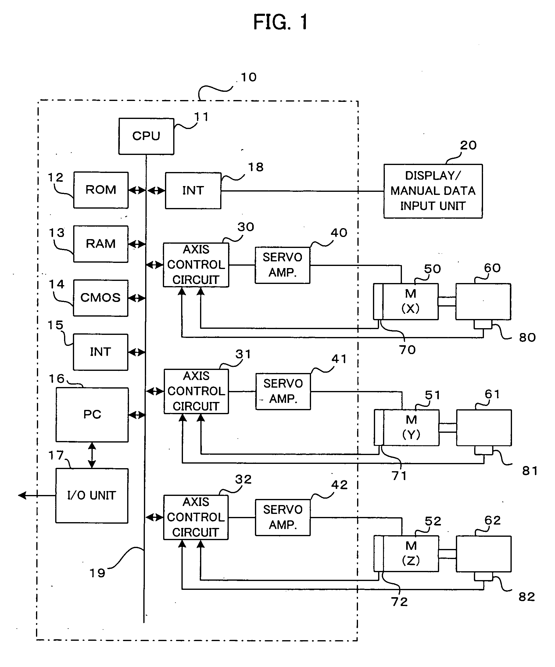
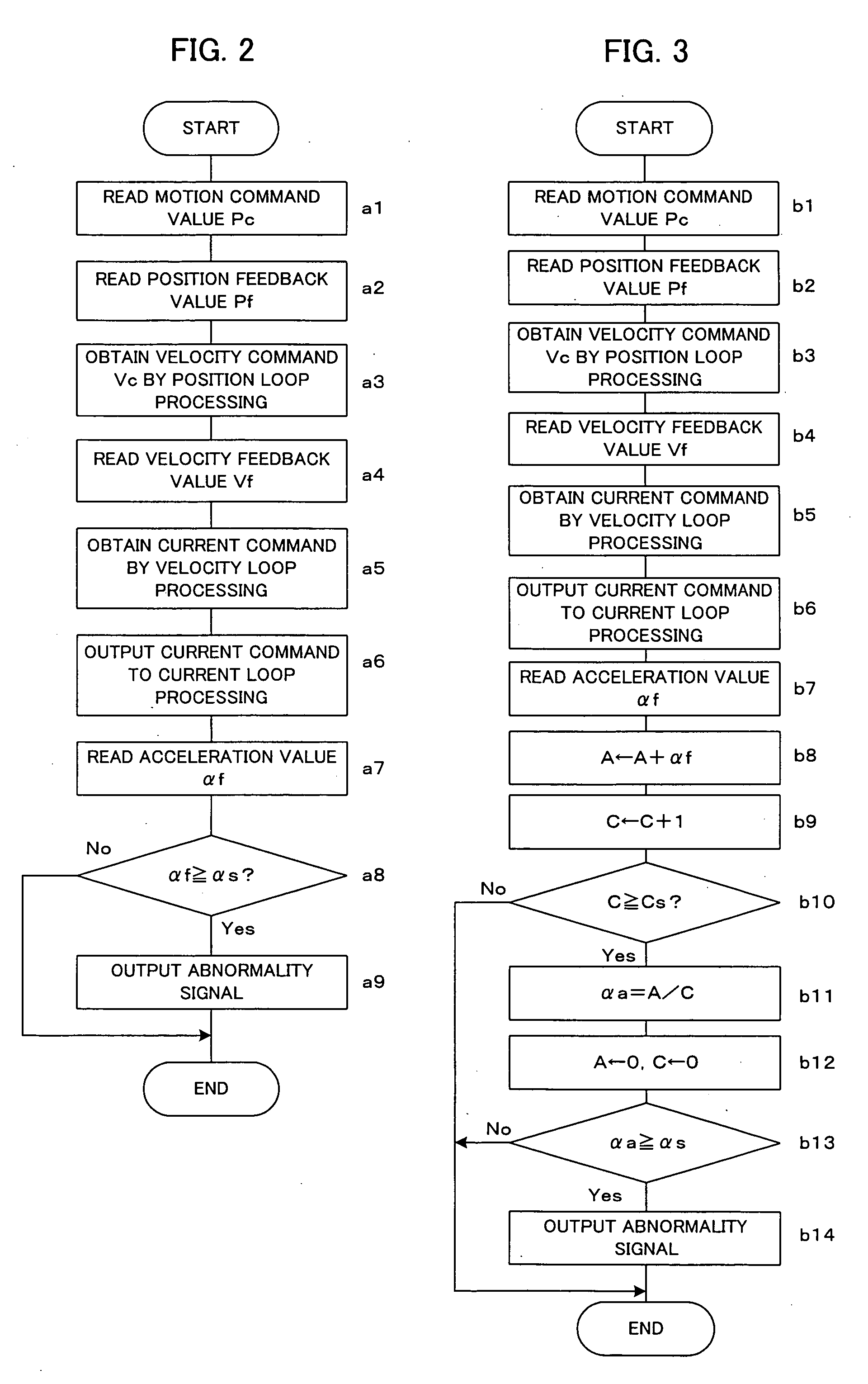
[0037]FIG. 2 is a flowchart showing processing to be executed by respective processors of control circuits 30 to 32 at every position / velocity control period according to the present invention.

[0038] In this first embodiment, the control circuits 30 to 32 determine whether the driven elements driven by their corresponding servomotors are subject to vibration that causes abnormal operation. In case of abnormality, an abnormality signal is outputted to the CPU 11 as a host processor.

[0039] Each of the processors of the control circuits 30 to 32 reads a motion command value Pc from the CPU 11 that performs numerical control processing such as distribution of motion commands, reads a position feedback value Pf from the position / velocity detector 70 to 72, and obtains a velocity command Vc by position loop processing (position feedback processing) (Steps a1, a2 and a3). Further, each of the processors reads a velocity feedback value Vf from the associated one of the position / velocity de...

sixth embodiment

[0057] If any portions of the machine are subjected to secular change and reduced in mechanical strength, owing to prolonged use of the machine, the bed of the machine that supports the driven elements sometimes may vibrate as the driven elements move. If the driven elements collide or interfere with other objects, moreover, it causes the machine to vibrate. In the sixth embodiment, this vibration is detected to detect the machine abnormality.

[0058] In the sixth embodiment, the acceleration detecting means (not shown) are attached to the machine bed, and their outputs are captured into the controller 10 through an interface. The CPU 11 of the controller 10 determines the machine abnormality by the captured detected acceleration values af.

[0059]FIG. 7 is a flowchart showing machine abnormality determination processing to be executed by the CPU 11 at every given period in the sixth embodiment.

[0060] The CPU 11 reads the detected acceleration value af outputted from the acceleration ...


PUM


Abstract

Disclosed is a controller for detecting need of maintenance, abnormal operation, etc. of a machine attributable to reduction of its strength caused by secular change. Acceleration detecting means are attached to driven elements that are driven by servomotors. Respective processors of axis control circuits for feedback-controlling the positions and velocities of the servomotors perform position and velocity feedback control processing for each position/velocity control period, thereby obtaining current commands, and output the commands to current loop processing. Detected acceleration values af are read from the acceleration detecting means. When the detected acceleration values af are not smaller than a threshold value as, an abnormality signal is outputted, whereupon an alarm is displayed and the machine operation is stopped. Since the accelerations of the driven elements are detected directly by the acceleration detecting means, abnormality of the machine, such as frequent vibration attributable to aging of the machine, collision of the driven elements with other objects, or breakage of parts, can be detected securely.

Description

BACKGROUND OF THE INVENTION [0001] 1. Field of the Invention [0002] The present invention relates to a controller for controlling a position and / or a velocity of a driven member in a machining apparatus such as a machine tool. [0003] 2. Description of the Related Art [0004] In a machining apparatus, such as a machine tool, a tool is moved relatively to a workpiece to be machined as machining is performed. In order to control the position and velocity of machining, driven elements (workpiece, table on which the workpiece, tool, etc.) are driven by servomotors, and their positions and velocities are normally controlled by position, velocity, and current feedbacks. [0005] With the driven elements driven by the motors for position and velocity control, the machine gradually becomes more easily swingable with time as it continues to be used. Depending on its individual difference, the machine is reduced in strength, so that the operational accuracy for position and velocity lowers. In th...

Claims


Application Information

Patent Timeline
IPC IPC(8): G05B13/02
CPCG05B19/4062
Inventor IWASHITA, YASUSUKEOKITA, TADASHIKAWAMURA, HIROYUKIIKAI, SATOSHI
Owner FANUC LTD
Why Eureka
Try Eureka