Object detection system for vehicle

a technology for object detection and vehicles, applied in anti-collision systems, non-deflectable wheel steering, underwater vessels, etc., can solve the problems of system failure to track a vehicle, system failure to generate false positive detections, and inability to continuously handle expensive processing controls and computationally expensive software. , to achieve the effect of reducing the possibility of false positive signals and processing requirements

Active Publication Date: 2006-08-17
MAGNA ELECTRONICS
View PDF91 Cites 299 Cited by
  • Summary
  • Abstract
  • Description
  • Claims
  • Application Information

AI Technical Summary

Benefits of technology

[0008] The present invention is intended to provide an object detection system, such as a blind spot detection system, a lane change assist or aid system or device, a lane departure warning system, a side object detection system, a reverse park aid system, a forward park aid system, a forward, sideward or rearward collision avoidance system, an adaptive cruise control system, a passive steering system or the like, which is operable to detect and/or identify a vehicle or other object of interest at the side, front or rear of the vehicle equipped with the object detection system. The object detection system of the present invention, such as for a lane change assist system, utilizes an edge detection algorithm to detect edges of objects in the captured images and determines if a vehicle is present in a lane adjacent to the equipped or subject vehicle in response to various characteristics of the detected edges, such as the size, locatio

Problems solved by technology

Because such systems typically use statistical methodologies to determine a likelihood or probability that a detected object is a vehicle, and for other reasons, the systems may generate false positive detections, where the system indicates that a vehicle is adjacent to, forward of or rearward of the subject vehicle when there is no vehicle adjacent to, forward of or rearward of the subject vehicle, or false negative detections, where the system, for example, indicates that there is no vehicle adjacent to the subject vehicle when there actually is a vehicle in the adjacent lane.
Such frame by frame flow algorithms and systems may not be able to track a vehicle which is moving at generally the same speed as the equipped vehicle, because there may be little or no relative movement between the vehicles and,

Method used


Image

  • Object detection system for vehicle
  • Object detection system for vehicle
  • Object detection system for vehicle

Examples


Embodiment Construction

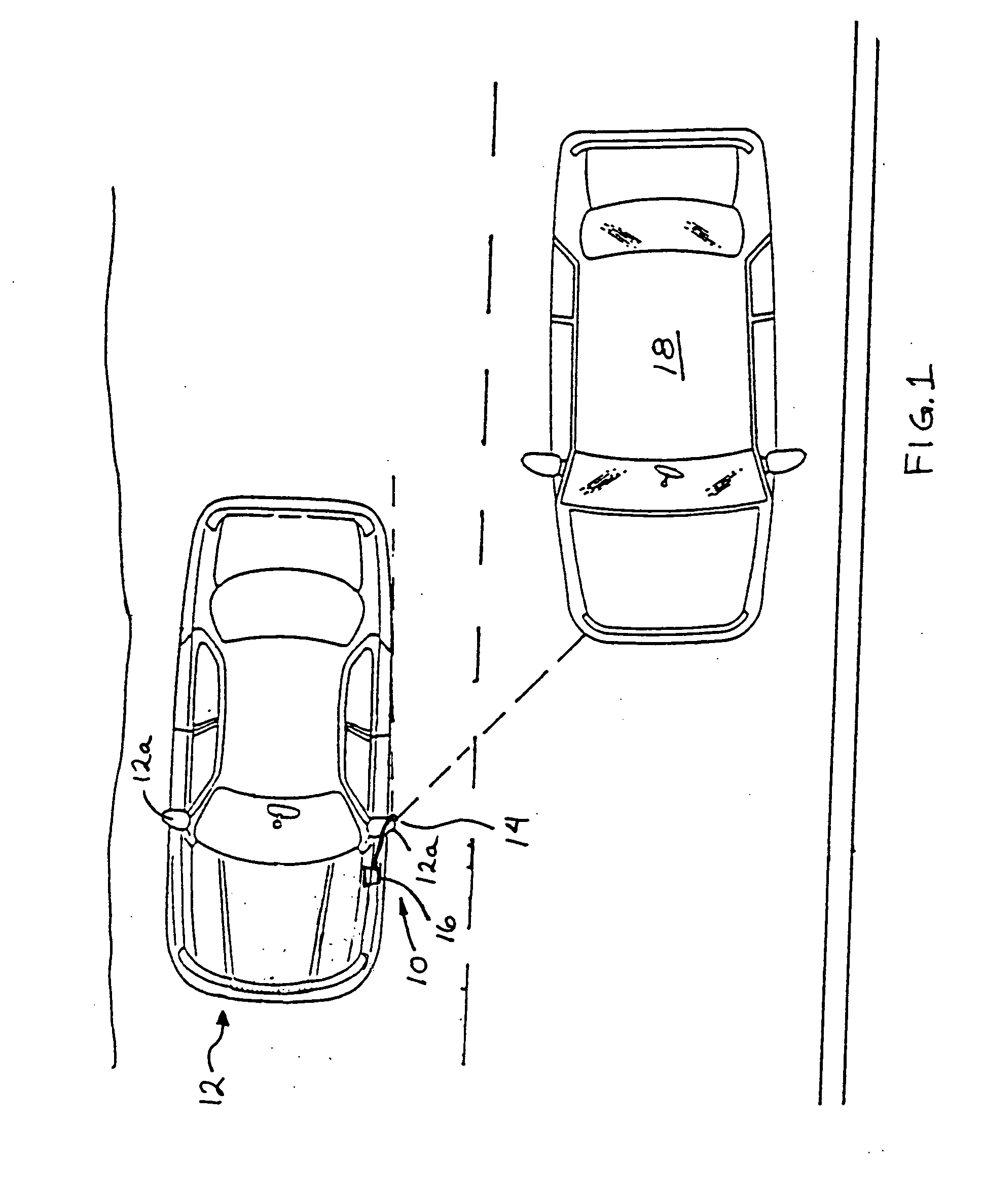
[0027] Referring now to the drawings and the illustrative embodiments depicted therein, an object detection system or imaging system, such as a lane change assist or aid system 10, is positioned at a vehicle 12 (such as at an exterior rearview mirror 12a of a vehicle) and is operable to capture an image of a scene occurring sidewardly and rearwardly at or along one or both sides of vehicle 12 (FIG. 1). Lane change assist system 10 comprises an image capture device or sensor or camera 14, which captures an image of the scene occurring toward a respective side of the vehicle 12, and a control 16, which processes the captured image to determine whether another vehicle 18 is present at the side of vehicle 12, as discussed below. Control 16 may be further operable to activate a warning indicator or display or signal device to alert the driver of vehicle 12 that another vehicle is present at the side of vehicle 12. The warning or alert signal may be provided to the driver of vehicle 12 in...


PUM


Abstract

An imaging system for a vehicle includes an imaging array sensor and a control. The image array sensor comprises a plurality of photo-sensing pixels and is positioned at the vehicle with a field of view exteriorly of the vehicle. The imaging array sensor is operable to capture an image of a scene occurring exteriorly of the vehicle. The captured image comprises an image data set representative of the exterior scene. The control algorithmically processes the image data set to a reduced image data set of the image data set. The control processes the reduced image data set to extract information from the reduced image data set. The control selects the reduced image data set based on a steering angle of the vehicle.

Description

CROSS REFERENCE TO RELATED APPLICATION [0001] The present application claims benefit of U.S. provisional application Ser. No. 60 / 638,687, filed Dec. 23, 2004 (Attorney Docket DON01 P-1195), which is hereby incorporated herein by reference in its entirety.FIELD OF THE INVENTION [0002] The present invention relates generally to vision or imaging systems for vehicles and is related to object detection systems and, more particularly, to imaging systems which are operable to determine if a vehicle or object of interest is adjacent to, forward of or rearward of the subject vehicle to assist the driver in changing lanes or parking the vehicle. The present invention also relates generally to a lane departure warning system for a vehicle BACKGROUND OF THE INVENTION [0003] Many lane change aid / side object detection / lane departure warning devices or systems and the like have been proposed which are operable to detect a vehicle or other object that is present next to, ahead of or rearward of th...

Claims


Application Information

Patent Timeline
IPC IPC(8): G05D1/00G06F17/10
CPCB60R1/00B60R2300/402B60R2300/802B60R2300/804B60R2300/806H04N5/374B60W40/04B60W50/14H04N7/18H04N5/23229B60R2300/8066B60Q9/008B60R1/12B60R2001/1253B60R2300/30G06V20/58G06V20/584H04N23/80H04N25/76G06V20/588B60R2300/105H04N7/181
Inventor HIGGINS-LUTHMAN, MICHAEL J.
Owner MAGNA ELECTRONICS
Why Eureka
Try Eureka