Diaphragm-sealed valve, analytical chromatographic system and method using the same

a technology of diaphragm and chromatographic system, which is applied in the direction of slide valve, component separation, instruments, etc., can solve the problems of limiting system performance, requiring a relatively large amount of room in the system, and requiring assembly, i.e. actuating means and valves, and achieving the effect of preventing fluid communication

Active Publication Date: 2006-08-24
APN INC
View PDF26 Cites 31 Cited by
  • Summary
  • Abstract
  • Description
  • Claims
  • Application Information

AI Technical Summary

Problems solved by technology

In both cases, these assemblies, i.e. actuating means and valve, require a relatively large amount of room in a system.
However, their performances are poor.
For example, the leak rate from port to port is too high and thus limits the system performance.
Moreover, the pressure drop on the valve's ports differs from port to port, causing pressure and flow variation in the system.
This causes detrimental effect on column performance and detector baseline.
Furthermore, many of them have too much inboard contamination.
Any difference in their lengths will result in leaks, since a shorter plunger will not properly compress the diaphragm against the interface 4.
However, as they reported in a more recent valve brochure specification entitled “Applied Automation Company, series 11 diaphragm valve”, this method has been dropped because of a too high cold flow.
However, such designs still result into too much leak rate between ports since the sealing done by the plungers' pressure is not equal on diaphragm.
The system, as far as we know, wasn't commercialized.
Cross port leaks are still an important problem.
Nevertheless, cross port leaks are still too high for modern high sensitivity detector.
All of the proposed designs are quite similar in regard to sealing mechanisms and have the same drawbacks.
Besides, a brand new diaphragm valve will often have too many leaks between ports for low level applications.
Moreover, it appears that when the valve is at rest for a long period of time, it doesn't perform well when put back in service.
It is even worst for valves having fine edge plungers defining a ring type sealing surface.
Thus, the diaphragm type gas chromatography valves of the prior art have several disadvantages: they present too much cross port leaks and too much pressure drop on selected adjacent ports.
Moreover, they are difficult to operate when sample pressure is low and they cannot conveniently work with sub-atmospheric sample pressure.

Method used


Image

  • Diaphragm-sealed valve, analytical chromatographic system and method using the same
  • Diaphragm-sealed valve, analytical chromatographic system and method using the same
  • Diaphragm-sealed valve, analytical chromatographic system and method using the same

Examples


Embodiment Construction

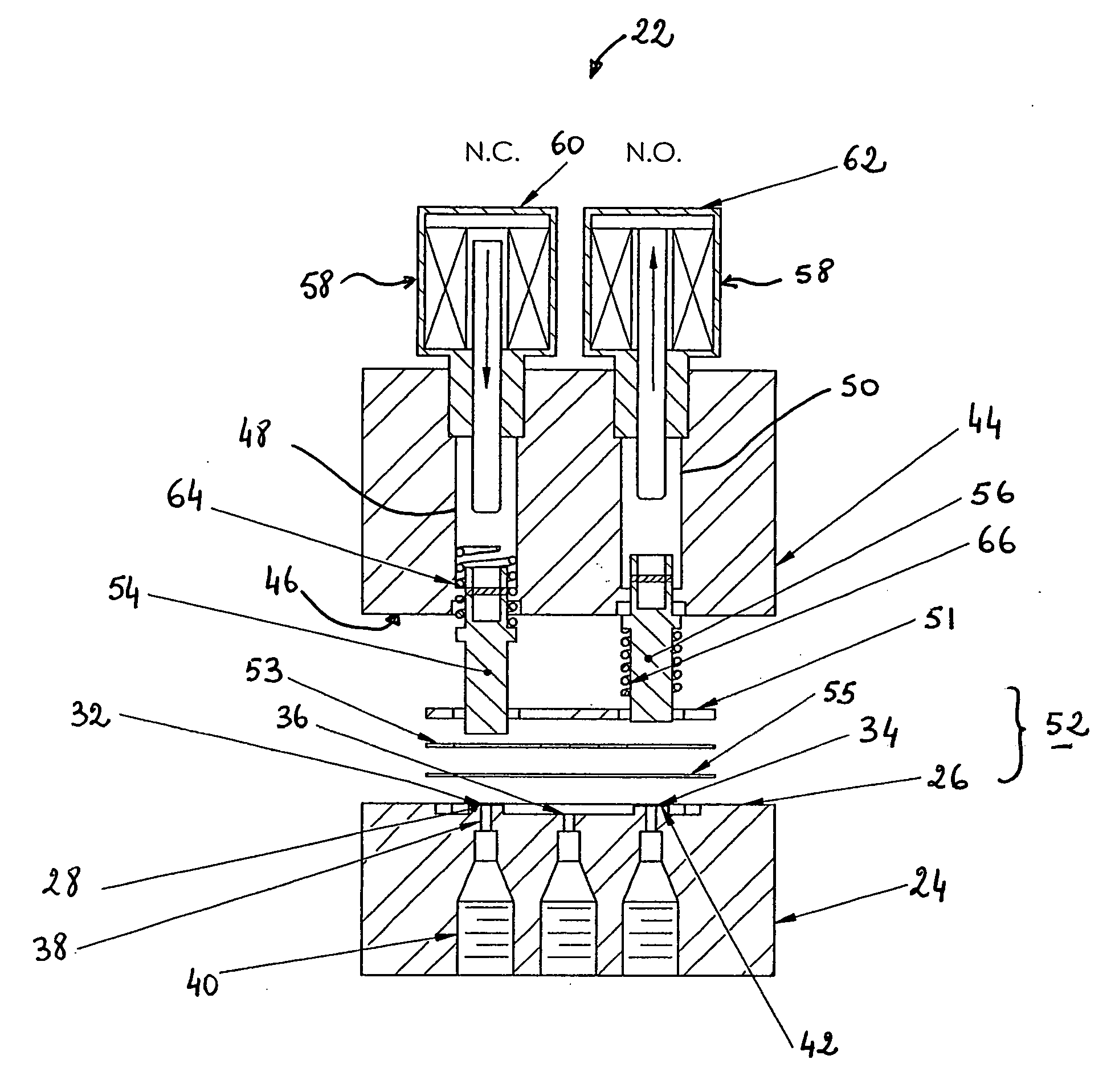
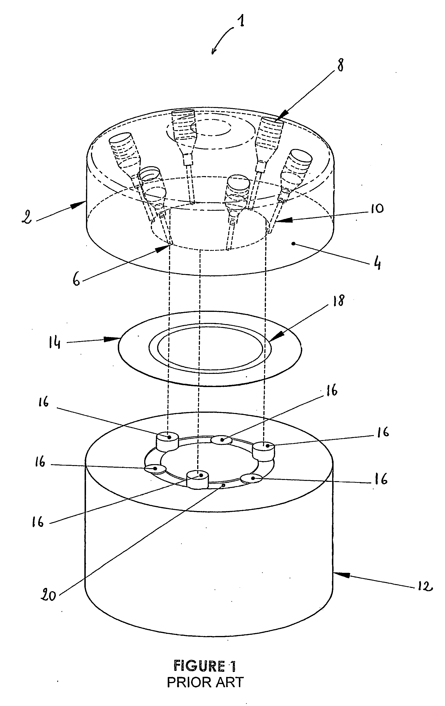
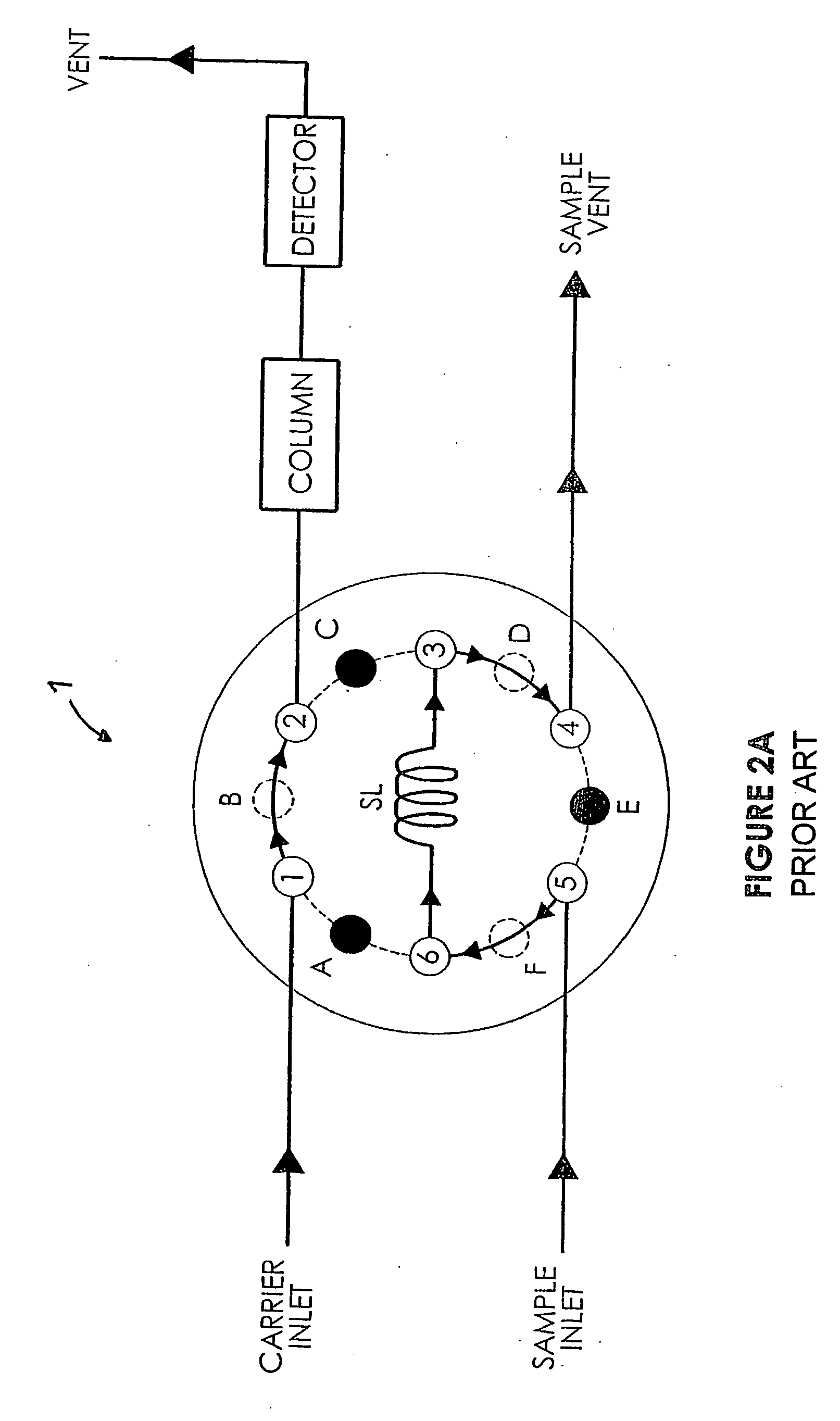
[0089] In the following description, similar features in the drawings have been given similar reference numerals and, in order to weight down the figures, some elements are not referred to in some figures if they were already identified in a precedent figure.

[0090] The present invention concerns a diaphragm-sealed valve, also referred to as a diaphragm based tight shut off valve, mostly dedicated for analytical equipments, and more particularly chromatographic equipments or on line analyzers. The present invention also concerns chromatographic systems and chromatographic methods based on the use of at least one diaphragm-sealed valve. As will be greater detailed herein below, these systems and methods are based on the use of at least one diaphragm-sealed valve, which, in a first preferred embodiment can be referred to as a three way switching cell. This switching cell has one common port and two actuated ports, these actuated ports being advantageously independently actuated. Thus,...


PUM

PropertyMeasurementUnit
shapeaaaaaaaaaa
lengthaaaaaaaaaa
pressureaaaaaaaaaa

Abstract

There is provided a diaphragm sealed valve particularly advantageous in chromatographic systems. The valve is provided with first and second body and a seal member compressibly positioned therebetween. The first body comprises a first, a second and a common port, each opening and being interconnected to the others in a recessed fluid communication channel extending in a first interface of the first body. The valve is also provided with first and second plungers, each having a closed position wherein the plunger presses down the seal member against the seat of the corresponding port for closing said corresponding port, and an open position wherein the plunger extends away from the seat for allowing a fluid communication between the corresponding port and the channel. Complex valves are also provided as well as chromatographic systems and methods.

Description

FIELD OF THE INVENTION [0001] The present invention generally relates to a diaphragm-sealed valve for fluid analytical systems, and more particularly concerns a diaphragm-sealed valve having improved characteristics. The present invention also concerns an analytical chromatographic system and an analytical chromatographic method using such a diaphragm-sealed valve. BACKGROUND OF THE INVENTION [0002] As well known from people involved in the art, chromatographic systems rely on the use of valves to allow reproducible sample introduction and various column switching schemes. [0003] Today, in the chromatographic field, there are mainly two types of valves used: the rotary valves and the diaphragm-sealed valves. The rotary type, as the name suggests, uses a rotary movement to switch or divert various flow paths required for a particular application. Description of such valves may be found in U.S. patent application Ser. No. 10 / 957,560 filed on Oct. 1, 2004 by the same Applicant. [0004] ...

Claims


Application Information

Patent Timeline
Patent Type & Authority Applications(United States)
IPC IPC(8): G01N30/20F16K7/00F16K11/22
CPCF16K7/14F16K11/24G01N30/20G01N2030/205Y10T137/4259Y10T137/87249
Inventor GAMACHE, YVESFORTIER, ANDRE
Owner APN INC
Why Eureka
Try Eureka