System and method for collecting carbon dioxide in exhaust gas

Inactive Publication Date: 2006-08-24
KK TOSHIBA
View PDF7 Cites 51 Cited by
  • Summary
  • Abstract
  • Description
  • Claims
  • Application Information

AI Technical Summary

Benefits of technology

[0015] According to the method for recovery of the carbon dioxide contained in the exhaust gas, the carbon dioxide deposits as the insoluble compound, and the alkaline liquid absorbent which still has a

Problems solved by technology

However, Japan is already in a severe situation that full efforts must be exerted to achieve the target because the emission has increased by 8% as of the year 2000.
The above-described conventional car

Method used


Image

  • System and method for collecting carbon dioxide in exhaust gas
  • System and method for collecting carbon dioxide in exhaust gas
  • System and method for collecting carbon dioxide in exhaust gas

Examples


first embodiment

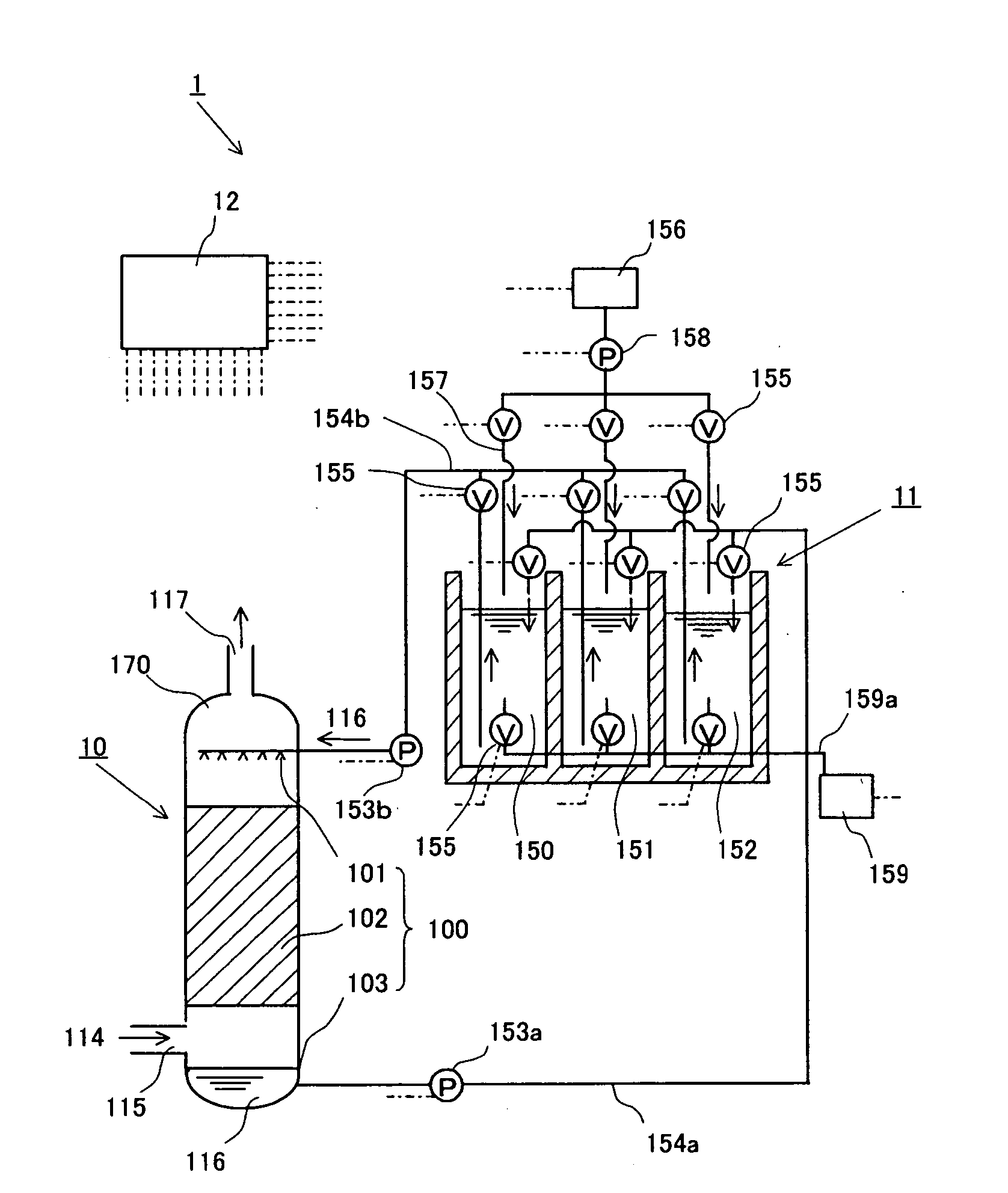
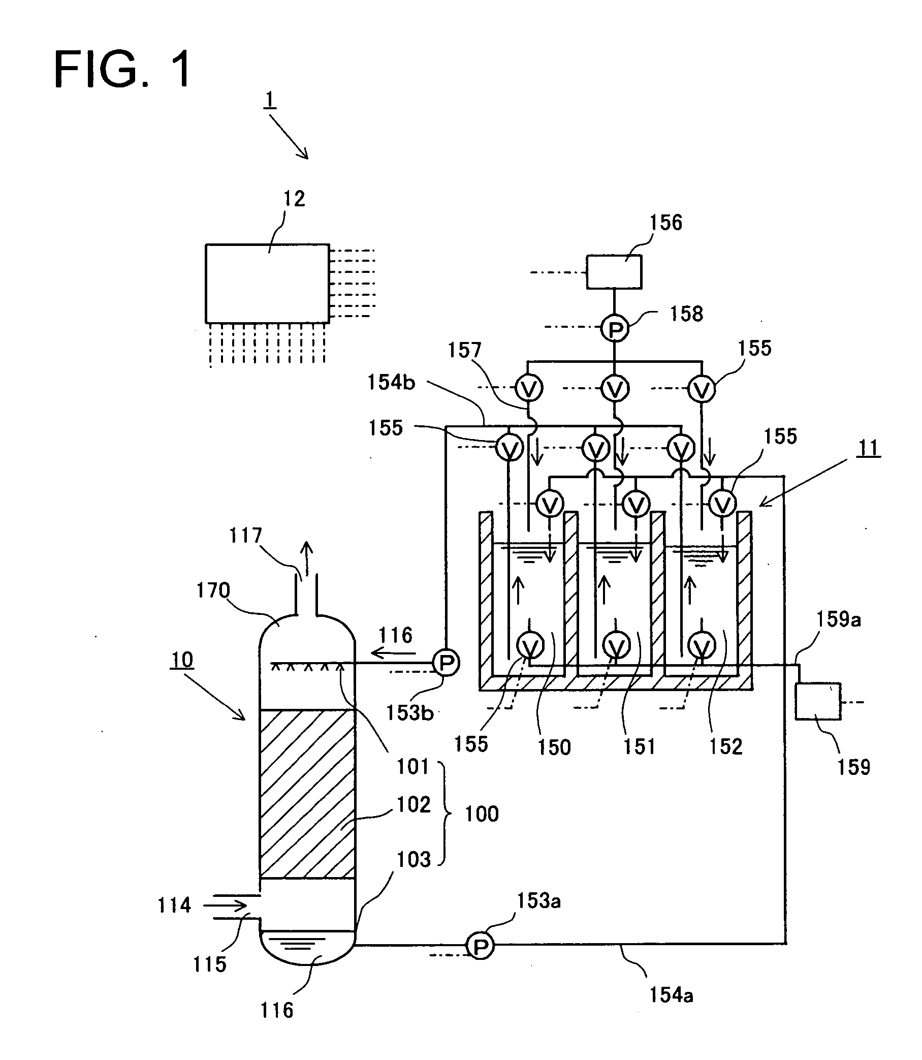
[0020]FIG. 1 shows an overview of a carbon dioxide recovery system 1 according to the first embodiment of the present invention. The carbon dioxide recovery system 1 of the first embodiment of the invention is mainly comprised of an absorber 10, a deposition vessel 11, and a control section 12. In FIG. 1, the control section 12 is electrically connected to individual pumps, individual valves and a concentration measuring instrument to be described later, but connection lines are omitted for convenience of clear illustration.

[0021] The absorber 10 is provided at its lower part with an exhaust gas supply part 115 for guiding exhaust gas 114 containing carbon dioxide exhausted from thermal power stations, municipal waste incineration plants and the like into the absorber 10. Within the absorber 10 is disposed an absorption section 100 which absorbs the carbon dioxide from the exhaust gas 114 which is introduced from the exhaust gas supply part 115. In addition, the absorber 10 is prov...

second embodiment

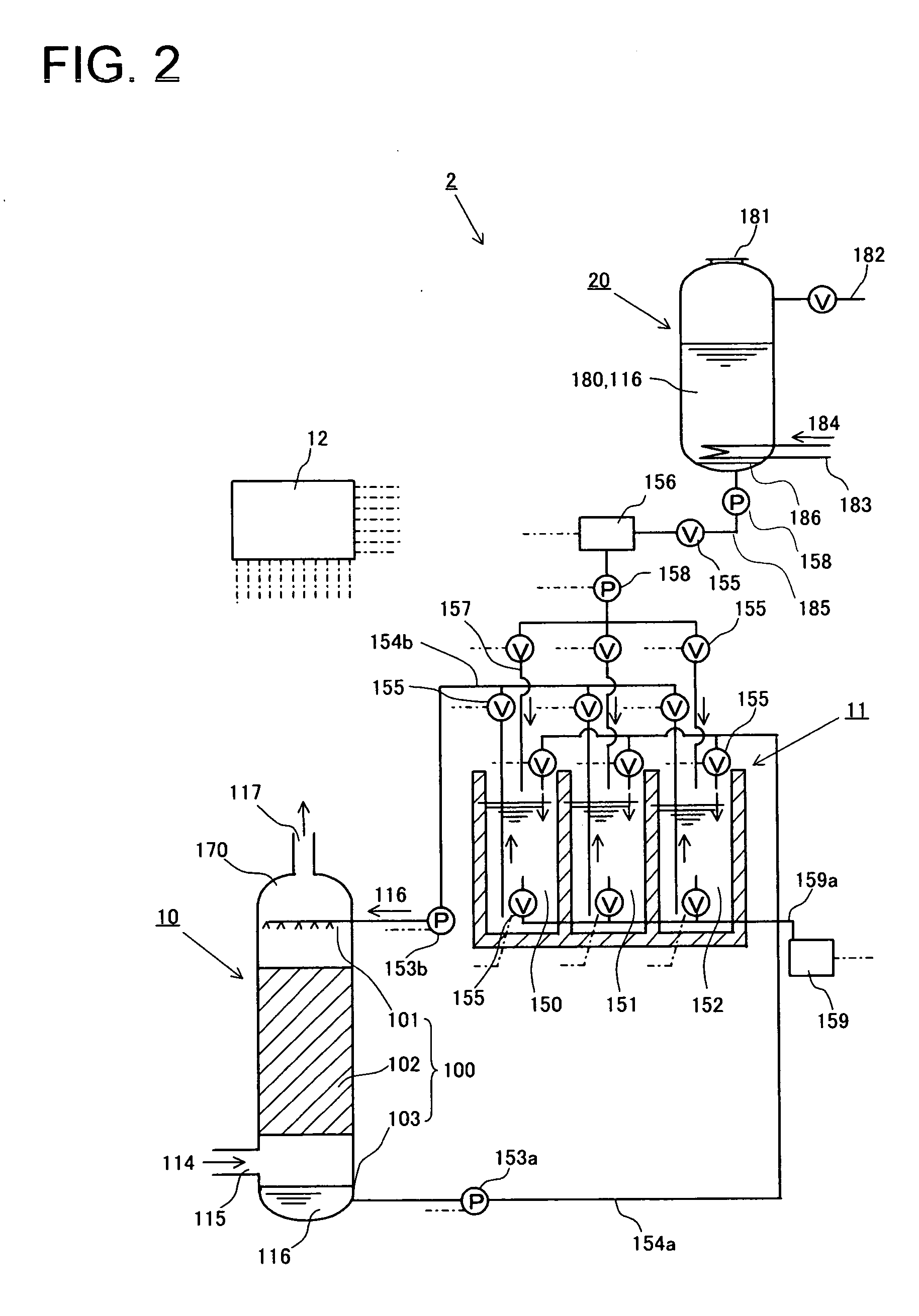
[0046]FIG. 2 is a general view of a carbon dioxide recovery system 2 with a regenerator 20, which regenerates the liquid absorbent 116 by heating insoluble compounds 180, added to the carbon dioxide recovery system 1 of the first embodiment of the present invention. Like parts as those of the carbon dioxide recovery system 1 of the first embodiment are denoted by like reference numerals, and overlapped descriptions will be omitted.

[0047] A charging port 181 for the insoluble compounds 180, which are a reaction product of the liquid absorbent 116 and the carbon dioxide, and a carbon dioxide outlet line 182 are disposed on upper parts of the regenerator 20, and a hot water pipe 183 is disposed at a lower part of the regenerator 20. The regenerator 20 is not connected to the circulation pipes 154a, 154b. And, a liquid absorbent supply pipe 185 having the pump 158 and the valve 155, which are connected to the liquid absorbent replenishing section 156, is connected to the bottom of the ...


PUM

PropertyMeasurementUnit
Concentrationaaaaaaaaaa

Abstract

A system and a method for recovery of carbon dioxide in exhaust gas, wherein a liquid absorbent (116) jetted from a liquid absorbent jetting part (101) comes into gas-liquid contact with exhaust gas (114) flowing through a packing (102) from the lower side to the upper side to absorb the carbon dioxide contained in the exhaust gas (114). The flow of the liquid absorbent (116) in a deposition vessel (11) conditioned to a specified pH value is stopped to deposit insoluble compounds as the reaction product of the liquid absorbent (116) against the carbon dioxide, and the carbon dioxide is collected as the insoluble compounds. Thus, the carbon dioxide can be removed from the liquid absorbent which absorbed the carbon dioxide without using steam from a power generating boiler.

Description

TECHNICAL FIELD [0001] The present invention relates to a carbon dioxide recovery system for recovering carbon dioxide contained in exhaust gas discharged from thermal power stations, municipal waste incineration plants and the like, and more particularly to a system and a method for recovery of carbon dioxide contained in exhaust gas that can recover the carbon dioxide by an alkaline liquid absorbent. BACKGROUND ART [0002] In these years, significant concerns in connection with combustion products from the burning of fossil fuels include a global warming issue caused by greenhouse gases such as carbon dioxide. According to the Kyoto Protocol to the United Nations Framework Convention on Climate Change, Japan is required to reduce the greenhouse gas emission through the years 2008-2012 to a level 6% below the total emission in 1990. However, Japan is already in a severe situation that full efforts must be exerted to achieve the target because the emission has increased by 8% as of t...

Claims


Application Information

Patent Timeline
IPC IPC(8): B01D53/14B01D53/34B01D53/62C01B32/50
CPCB01D53/62Y02C10/04Y02C10/06Y02C20/40
Inventor MORIYAMA, HIDESHIGEMATSUNAGA, KENTAROFUKUDA, MASAFUMI
Owner KK TOSHIBA
Why Eureka
Try Eureka