Handle assembly for hammer apparatus

a technology of hammer and handle, which is applied in the direction of shock absorbers, portable power-driven tools, manufacturing tools, etc., can solve the problems of large vibration and detrimental to the health of users

Inactive Publication Date: 2006-08-24
BLACK & DECKER INC
View PDF4 Cites 10 Cited by
  • Summary
  • Abstract
  • Description
  • Claims
  • Application Information

AI Technical Summary

Benefits of technology

[0010] This provides the advantage that a user can vary the force applied to the working m...

Problems solved by technology

Reciprocating hammers of this type generally cause a large amount of vibration...

Method used


Image

  • Handle assembly for hammer apparatus
  • Handle assembly for hammer apparatus
  • Handle assembly for hammer apparatus

Examples


second embodiment

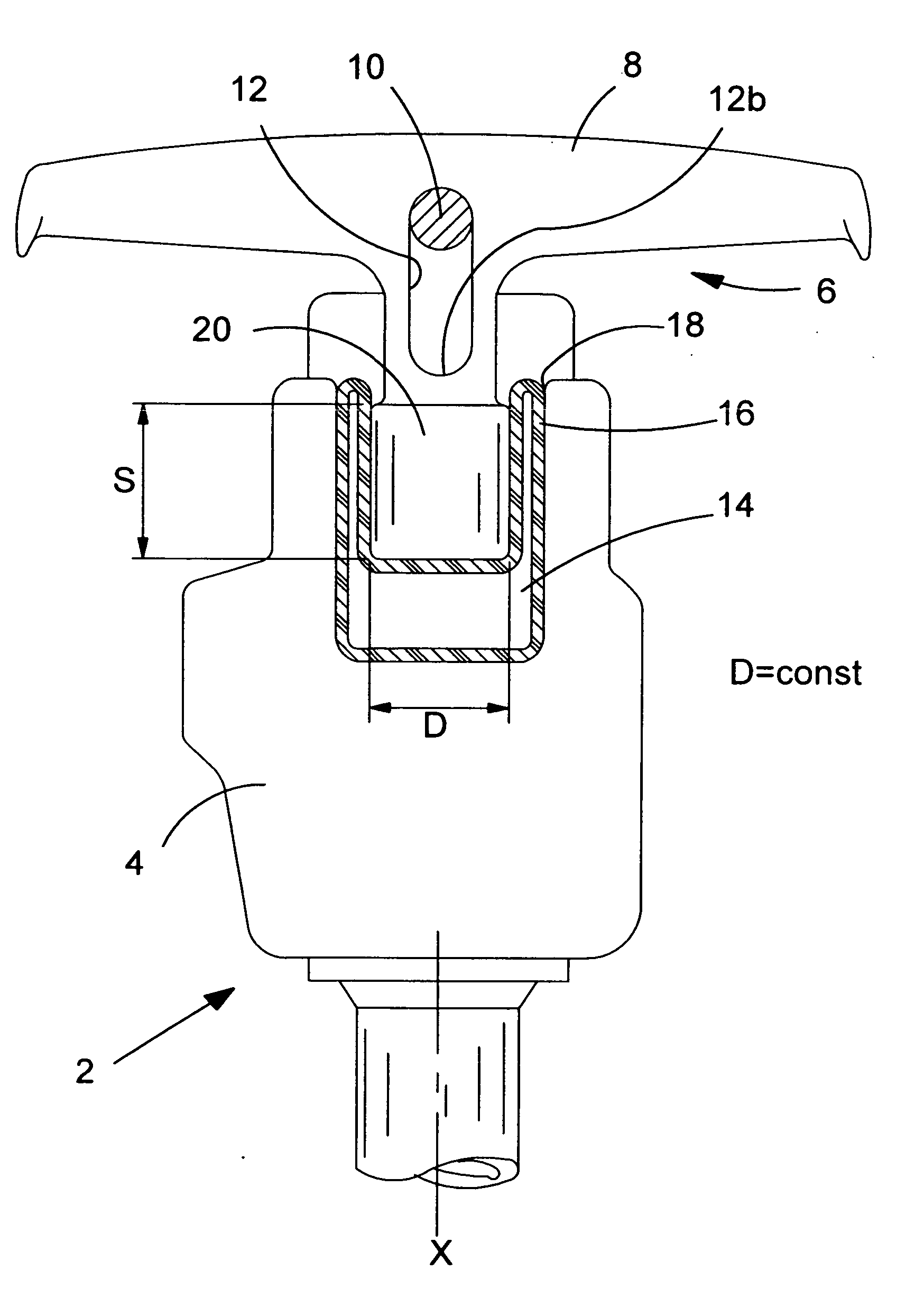
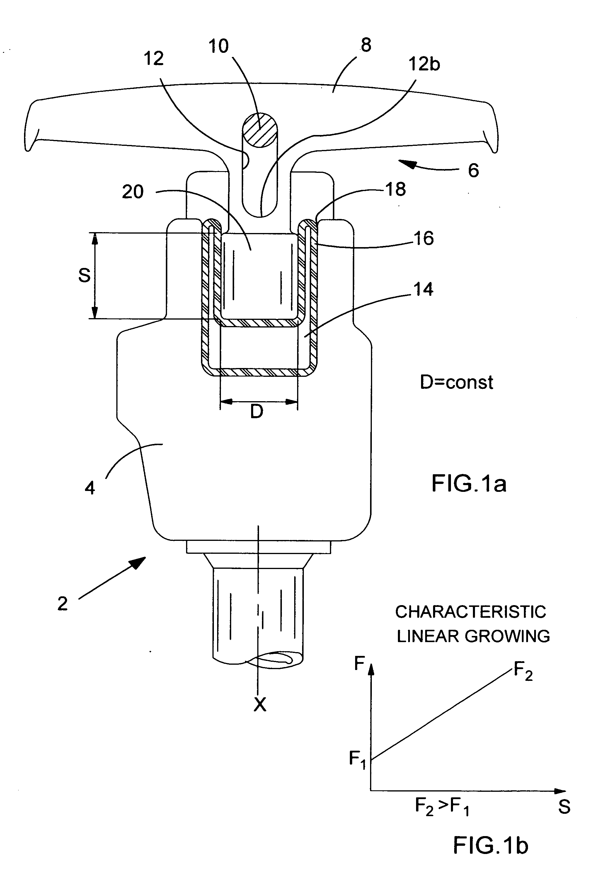
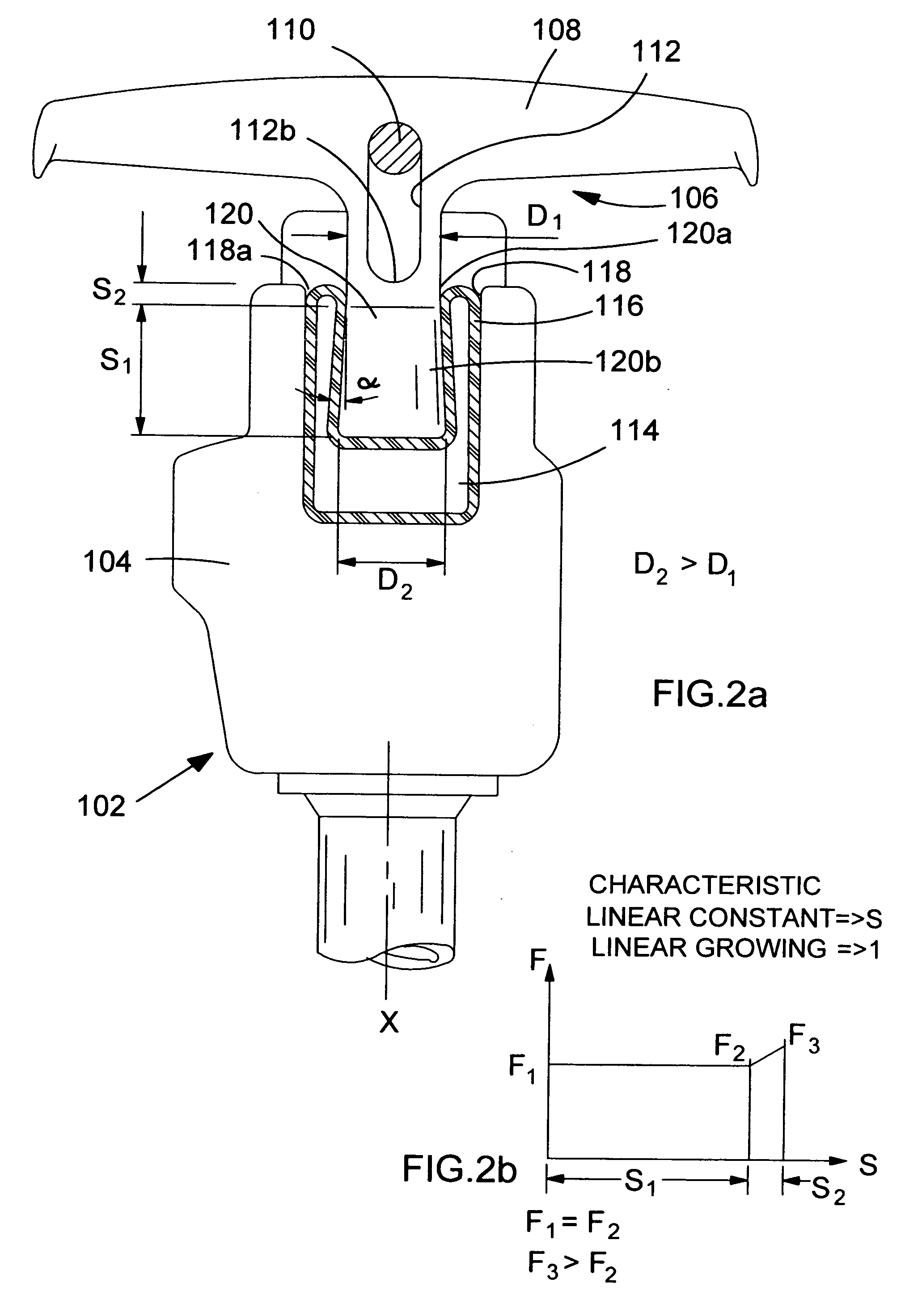
[0034] It has been found that changing the profile of engaging portion 20 changes the characteristic of force transmitted to the hammer housing versus distance of penetration of the engaging handle (and thus amount of compression of air chamber 14). a handle assembly 4 for the reciprocating hammer is shown in FIG. 2a. Parts common to the embodiment of FIG. 1 are shown with like reference numerals but increased by 100.

[0035] In this embodiment, the engaging member 120 of the handle assembly 106 is partially conical in shape. The diameter of the engaging member 120 increases from D1 at the upper most part of the engaging member 120 to a distance D2 at the lowermost part of the engaging member 120. This changes the characteristic (FIG. 2b) of force transmitted to the housing versus the extent to which the engaging member 120 is pushed into recess 118 and into engagement with the rubber membrane 116.

[0036] Engaging member 120 comprises two portions of different shape. A cylindrical por...

third embodiment

[0038] a handle assembly for a reciprocating hammer is shown in FIG. 3a, with parts common to the embodiment of FIG. 1 shown with like reference numerals but increased by 200.

[0039] The handle assembly 206 comprises handles 208 connected to an engaging member 220. The handle assembly 206 is slidably disposed on the hammer housing 204 by engagement of guide rod of 210 with elongate aperture 212. In this embodiment, engaging member 220 is partially conical in shape and has sides 222 disposed at an angle to axis X that converge on axis X from the uppermost part of engaging member 220 to the lowermost part. The diameter of the engaging member 220 at its uppermost point is D2, and its diameter at its lowermost point is D1.

[0040] This results in a non-linear characteristic of force transmitted to the reciprocating hammer by a user against the distance of insertion of engaging member 220 into recess 218 as shown in FIG. 2b. When engaging member 220 is located outside of recess 218 the for...

fourth embodiment

[0041] a handle assembly for a reciprocating hammer is shown in FIG. 4a, with parts common to the embodiment of FIG. 1 shown with like reference numerals but increased by 300.

[0042] In this embodiment engaging member 320 comprises a circumferential groove 324. This means that the engaging member 320 has a cylindrical portion 320a with sides that are disposed parallel to axis X, a converging portion 320b with sides that converge towards axis X, and a diverging portion 320c with sides that diverge away from axis X. This gives rise to the characteristic of transmitted force against distance of insertion of engaging member 320 shown in FIG. 4b.

[0043] A first region S1 on the graph represents a user pushing handles 308 to move diverging portion 320c of engaging member 320 past opening 318a of recess 318 to compress air cushion 314. Here, the curve of force against distance is flat and F1=F2. This is consistent with the behaviour of an engaging member having diverging sides such as that...


PUM


Abstract

A handle assembly for a reciprocating hammer tool comprises a handle for gripping, a guide rod, and an elongate aperture which slidably engages the guide rod to ensure that the handle assembly is aligned with the hammer. The handle assembly also comprises an air filled chamber bounded by a rubber membrane and disposed in a recess in the hammer housing. The air filled chamber is adapted to damp vibration during use of the reciprocating hammer. An engaging member formed integrally with handle is disposed adjacent the rubber membrane. The engaging member can move from a position in which the engaging member is inserted into the recess and fully compresses the air chamber, to a position in which the handle is pulled upwardly until the guide rod abuts the bottom edge of the elongate aperture. In this later position, the air chamber is placed under minimum compression.

Description

FIELD OF THE INVENTION [0001] The present invention relates to a handle assembly for a hammer apparatus and relates particularly, but not exclusively, to a handle assembly for a powered reciprocating hammer having a damping means to reduce the transmission of vibration to a user, and more particularly to a pavement breaker. BACKGROUND OF THE INVENTION [0002] Powered reciprocating hammers are known which have an electric motor that drives a hollow piston. A beat piece is disposed in the hollow piston and is caused to oscillate under an air spring effect such that the beat piece strikes an end of a bit to cause a hammering action. [0003] Reciprocating hammers of this type generally cause a large amount of vibration, which can be transmitted to a user and can be detrimental to the health of a user. [0004] Preferred embodiments of the present invention seek to provide a handle assembly for a hammer in which the amount of vibration transmitted to a user of an apparatus incorporating the ...

Claims


Application Information

Patent Timeline
IPC IPC(8): B25D17/24B25D17/04B25F5/00F16F9/04F16F15/023
CPCB25D17/043B25F5/006F16F9/0436F16F15/0232
Inventor BECHT, REIMUND
Owner BLACK & DECKER INC
Why Eureka
Try Eureka