

Semiconductor device
a technology of semiconductor devices and semiconductors, applied in semiconductor devices, semiconductor/solid-state device details, electrical apparatus, etc., can solve the problems of large transmission loss generated by transmitting a high-frequency signal, complex design of support substrates, and reduced packaging density of support substrates, etc., to prevent transmission loss of high-frequency signals, improve the efficiency of electronic devices, and increase packaging density
- Summary
- Abstract
- Description
- Claims
- Application Information
AI Technical Summary
Benefits of technology
Problems solved by technology
Method used
Image

Examples
first embodiment
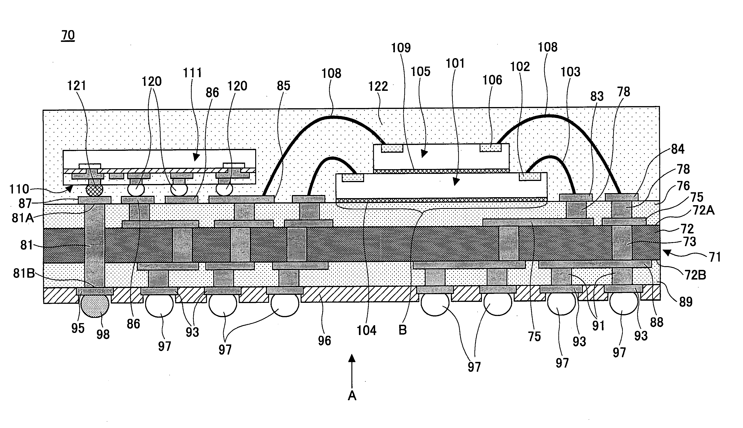
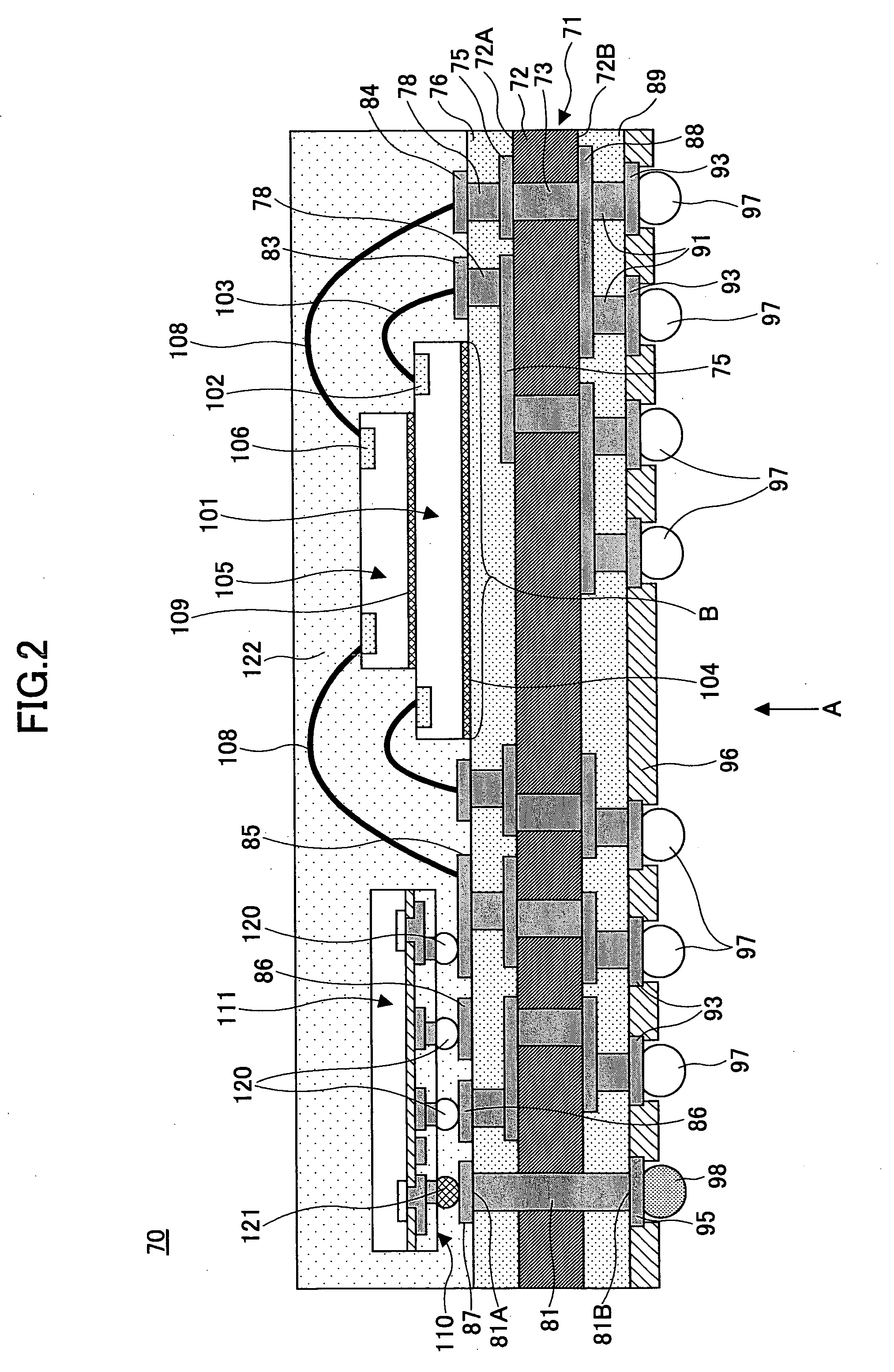
[0054] First, referring to FIGS. 2-4, a semiconductor device 70 according to a first embodiment of the present invention is described.
[0055]FIG. 2 is a cross-sectional diagram showing a configuration of the semiconductor device 70 according to the first embodiment; and FIG. 3 is a cross-sectional diagram showing a state in which the semiconductor device 70 is mounted on a mounting substrate.
[0056]FIG. 4 is a bottom plan view of the semiconductor device 70 viewed from the direction indicated by arrow A of FIG. 2.
[0057] It is noted that in FIG. 2, a region B is shown that corresponds to a region of an upper insulating film 76 on which a semiconductor element 101 is mounted (referred to as ‘chip mounting region B’ hereinafter).
[0058] According to the present embodiment, the semiconductor device 70 includes a support substrate 71, external connection terminals 97 and 98, semiconductor elements 101 and 105 corresponding to a first semiconductor element, and a high frequency semicondu...
second embodiment
[0141] In the following, a semiconductor device 135 according to a second embodiment of the present invention is described with reference to FIG. 11. It is noted that the semiconductor device 135 according to the present embodiment is characterized by implementing a shield member covering the high frequency semiconductor element.
[0142] In FIG. 11, components of the semiconductor device 135 that are identical to those of the semiconductor device 70 of the first embodiment are assigned the same references.
[0143] As is shown in FIG. 11, the semiconductor device 135 includes a support substrate 71, external connection terminals 97, 98, semiconductor elements 101, 105, a high frequency semiconductor element 110, and a shield member 136 covering the high frequency semiconductor element 110.
[0144] The semiconductor elements 101, 105, and the shield member 136 covering the high frequency semiconductor element 110 are covered by molded resin 122 along with wires 103 and 108.
[0145] In thi...
third embodiment
[0148] In the following, a semiconductor device 140 according to a third embodiment of the present invention is described with reference to FIGS. 12 and 13.
[0149]FIG. 12 is a cross-sectional diagram showing a configuration of the semiconductor device 140 according to the present embodiment. FIG. 13 is an enlarged cross-sectional diagram showing a configuration of a high frequency semiconductor element 145 of the semiconductor device 140 of FIG. 12. It is noted that the semiconductor device 140 according to the present embodiment is characterized in that it includes a capacitor element that is mounted on a rewiring formation surface of the high frequency semiconductor element 145.
[0150] It is noted that in FIGS. 12 and 13, components that are identical to those of the semiconductor device according to the first and second embodiment are assigned the same references.
[0151] Referring to FIG. 12, the semiconductor device 140 according to the present embodiment includes a support subs...
PUM
 Abstract
Description
Claims
Application Information