Axle-supporting device

Inactive Publication Date: 2006-08-24
JTEKT CORP
View PDF8 Cites 16 Cited by
  • Summary
  • Abstract
  • Description
  • Claims
  • Application Information

AI Technical Summary

Benefits of technology

[0027] With the axle support device wherein the stator and the rotor are provided on the antifriction bearing, the suspension member and the axle member are rotated relative to each other with a sinusoidal voltage applied to the stator to rotate the outer ring of the bearing and the inner ring thereof relative to each other, whereby an air gap between the stator and the rotor face to be detected is altered continuously or noncontinuously. This causes the stator to produce a voltage in accordance with the angle of rotation, whereby the state of rotation of the axle member can be detected contactlessly with high accuracy. When the axle support device is used for detecting rotation for ABS, the rotation is detectable with satisfactory accuracy as required even if the rotor face to be detected and opposed to the stator radially thereof is a simple eccentric cylindrical face or a cut-out cylindrical face as already mentioned, or even when the rotor face to be detected and opposed to the stator axially thereof is one of the side faces of various shapes mentioned. Thus, a lower cost can be achieved by giving the rotor a relatively simple detectable face. Furthermore, the stator and the rotor can be incorporated into the antifriction bearing in advance. This serves to reduce an increase in space due to the use of the stator, while the axle support device can be assembled as easily a

Problems solved by technology

However, the increase results in a lower magnetic flux density, entailing the problem that the absolute value of signal output of th

Method used


Image

  • Axle-supporting device
  • Axle-supporting device
  • Axle-supporting device

Examples


first embodiment

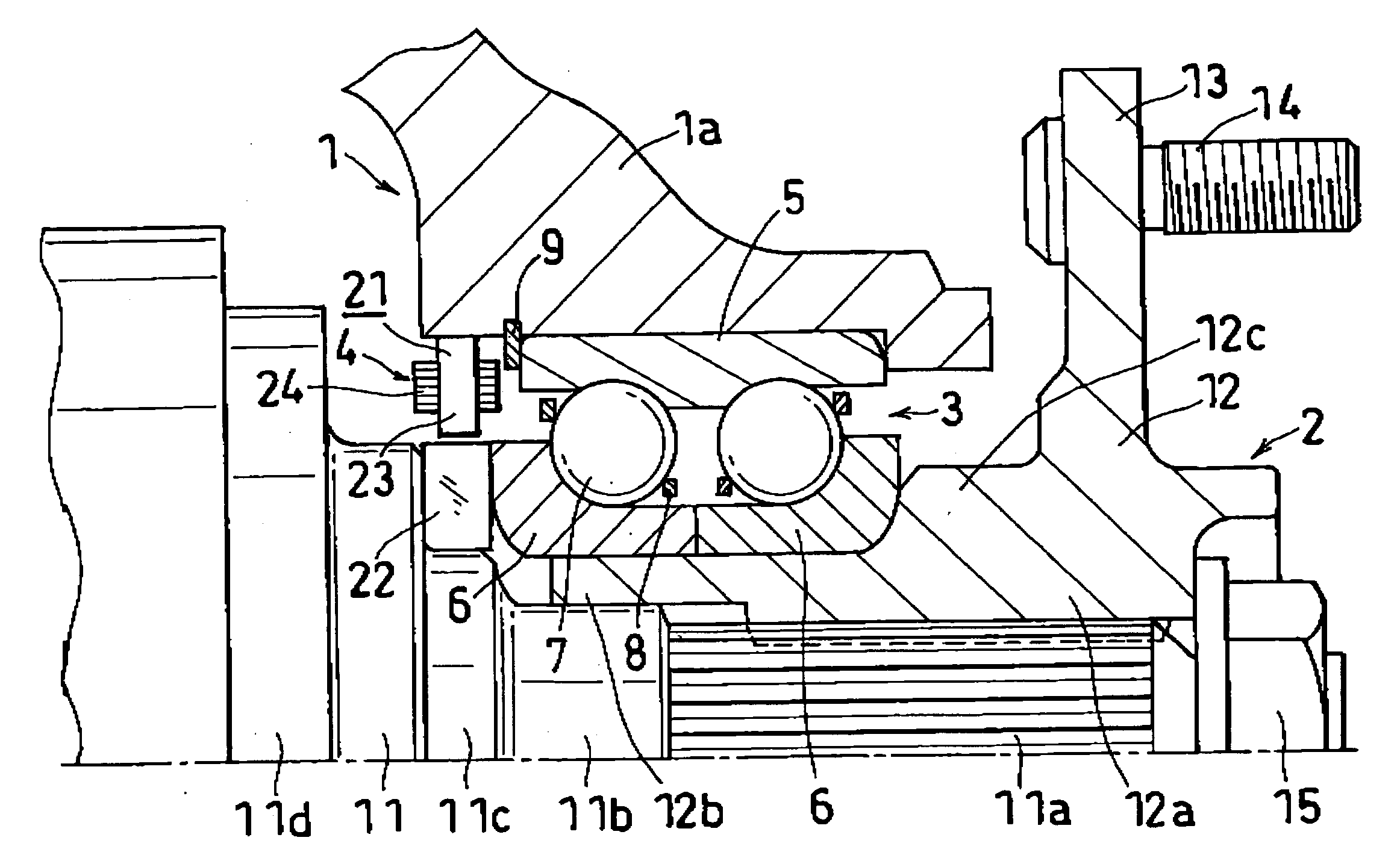
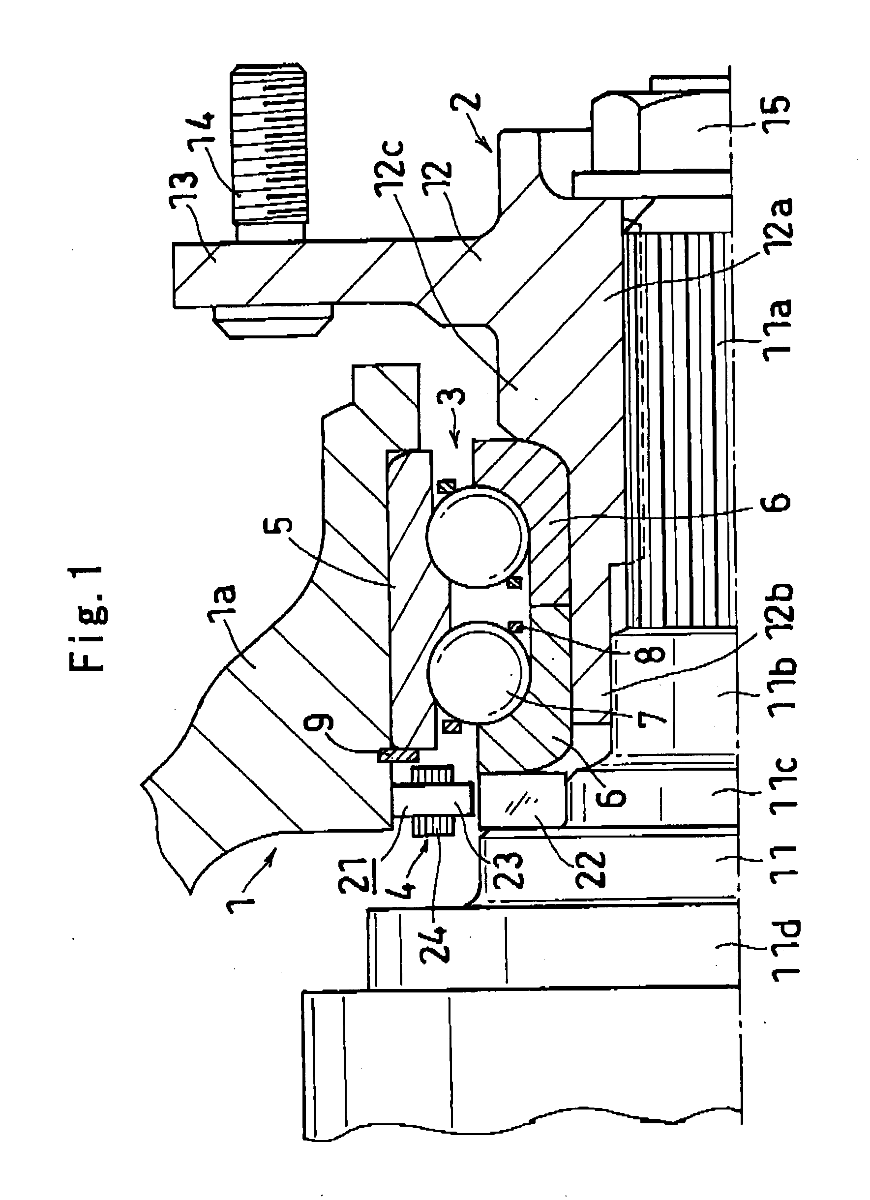
[0065]FIG. 1 shows the axle support device of a first embodiment, which comprises a suspension member 1 to be attached to a vehicle body; an axle member 2 for a wheel to be mounted thereon; an antifriction bearing 3 having an outer ring 5 attached to the suspension member 1, inner rings 6 mounted on the axle member 2, a plurality of rolling bodies 7 arranged between the raceway rings 5, 6 and retainers 8 for holding these rolling bodies 7; and a sensor device 4.

[0066] The antifriction bearing 3, which is a double-row angular ball bearing, has balls serving as the rolling bodies 7 and arranged in left and right two rows between the outer ring 5 and the inner rings 6. The outer ring 5 is an integral ring having two raceways, while the inner rings 6 are divided rings each having a single raceway. The outer ring 5 is fitted in the inner periphery of a knuckle 1a constituting the suspension member 1 and fixedly held by a stepped portion provided in the vicinity of the right end thereof, ...

seventh embodiment

[0088] When the axle member 2 rotates in the axle support device of the seventh embodiment, the gap between the sensor face of the stator 21 and the outer periphery of the outer ring 17 of the universal joint 16 (the face of the rotor 33 to be detected) varies for the stator 21 to produce voltage in accordance with the angle of rotation. Variations in the voltage of the stator 21 are sent to a processing circuit via the signal line. Further when the ground contact load on the tire varies, the displacement of the axle member 2 varies relative to the suspension member 1. This alters the air gap between the stator 21 and the outer periphery of the outer ring 17 of the universal joint 16, as detected by the resolver. As shown in FIG. 23, the variations in the air gap are output from the resolver as voltage variations, while the processing circuit of the resolver (sensor device) has a rotation detecting unit. This unit determines the angle of rotation or rotational speed required, for ex...

eighth embodiment

[0092] The sensor device 4 of this embodiment has a VR-type brushless resolver comprising a stator 26 and a rotor 44 for measuring axial displacements. The stator 26 is provided around the right end portion (axial end toward the wheel) of the knuckle 1a of the suspension member 1 by a press fit, with its sensor face directed outward axially thereof. With respect to the radial direction, the stator 26 is located at the same position as the pitch circle of wheel attaching bolts 14 provided on the flange portion 13 of the hub shaft 12. As is the case with the eighth embodiment, the wheel attaching bolts 14 each have a top face serving as the face of the rotor 43 to be detected. Four to six wheel attaching bolts 14 are provided at equal intervals, so that the distance (gap) between the stator 26 and the top faces of the wheel attaching bolts 14 has four to six peaks every turn of rotation. Accordingly, the number of revolutions is detectable by counting up four to six peaks as one revol...


PUM


Abstract

A sensor device 4 has a resolver comprising a stator 21 provided on a suspension member 1 and a rotor 31 provided on an axle member 2. The axle member 2 comprises a drive shaft 11 to be connected to a power transmission, and a hub shaft 12 having a wheel mount portion 13 and fixed to the drive shaft 11. The stator 21 is provided by a press fit on an axial end of knuckle 1a of the suspension member 1 toward a wheel, and the rotor 31 is provided by a press fit on the hub shaft 12 of the axle member 2. The stator 21 and the rotor 31 are opposed to each other radially thereof. An antifriction bearing 3 has rolling bodies 7 in left and right two rows, an outer ring 5 in the form of an integral ring having two raceways, and divided inner rings 6 each having a single raceway.

Description

TECHNICAL FIELD [0001] The present invention relates to axle support devices which comprise a device for supporting an axle of a motor vehicle for mounting a wheel thereon, and a sensor device attached to the device for detecting various items of data as to the motor vehicle. BACKGROUND ART [0002] Rotation sensor-equipped axle support devices are used in railroad cars and motor vehicles for supporting an axle or a rotating shaft for transmitting rotation to the axle and for detecting rotation, i.e., the speed of rotation of the axle or shaft or the angle of rotation thereof. Such devices comprise an antifriction bearing, and a sensor device and a pulser ring serving as a member to be detected, the sensor device and the pulsar ring being mounted on the bearing (see, the publication of JP-U No. 1-156463) [0003] It has been strongly required that the conventional rotation sensor-equipped axle support device be reduced in diameter and improved in the resolution involved in detecting rot...

Claims


Application Information

Patent Timeline
IPC IPC(8): B62D7/18B60B37/00G01P3/42F16C41/04F16C19/18F16C19/52G01P3/44
CPCF16C19/184F16C19/52G01P3/443G01P3/488F16C2326/02F16C41/007G01P3/44
Inventor KOYAGI, KATSURAWAKISAKA, TERUYUKIINOUE, MASAHIRO
Owner JTEKT CORP
Why Eureka
Try Eureka