

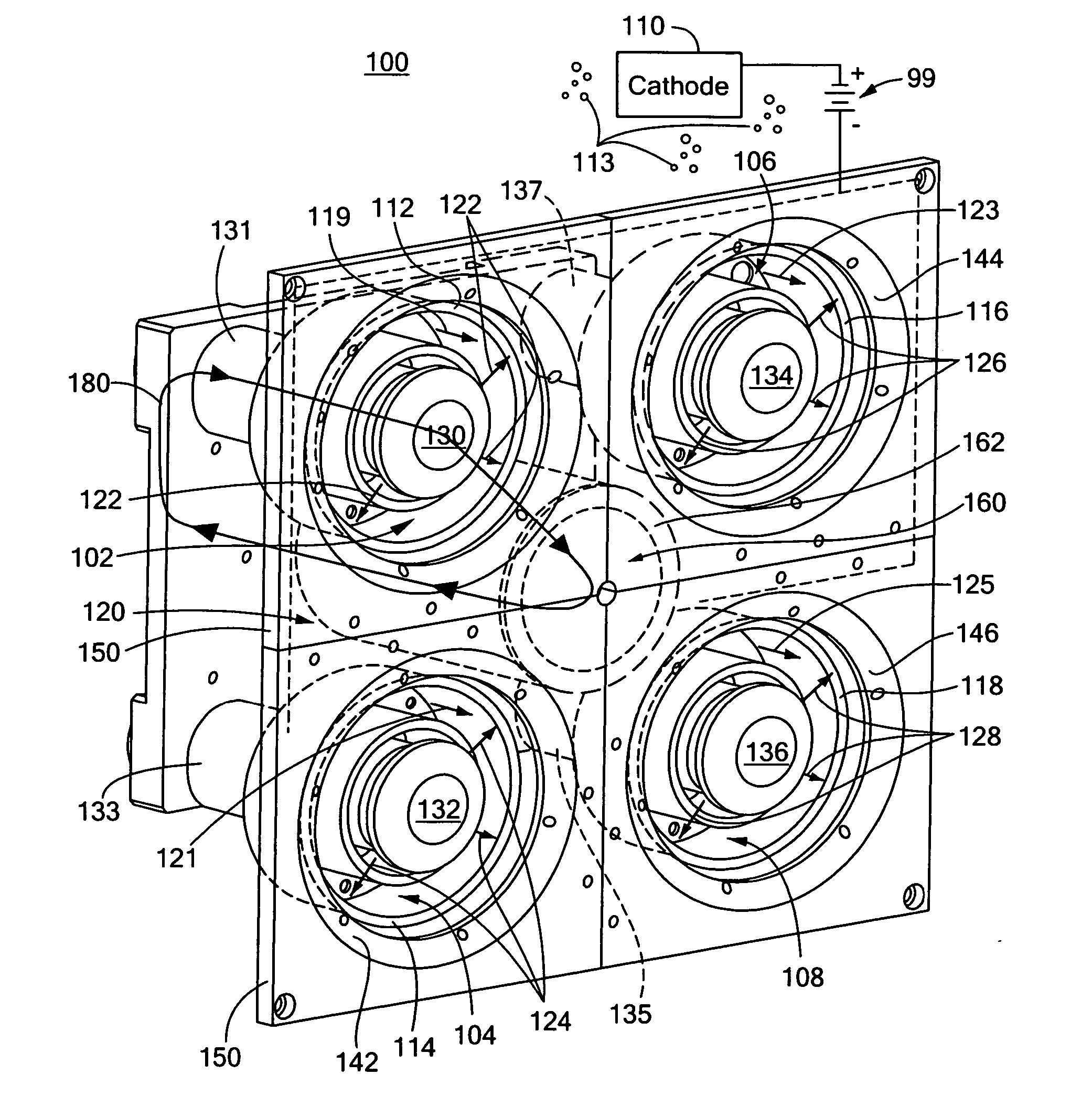
Hall thruster with shared magnetic structure
a technology of magnetic structure and thruster, which is applied in the field of hall thrusters, can solve the problems of complex, expensive, inefficient, and high cost, and achieve the effects of less expensive, less expensive, and less energy consumption
- Summary
- Abstract
- Description
- Claims
- Application Information
AI Technical Summary
Benefits of technology
Problems solved by technology
Method used
Image

Examples
Embodiment Construction
[0043] Aside from the preferred embodiment or embodiments disclosed below, this invention is capable of other embodiments and of being practiced or being carried out in various ways. Thus, it is to be understood that the invention is not limited in its application to the details of construction and the arrangements of components set forth in the following description or illustrated in the drawings. If only one embodiment is described herein, the claims hereof are not to be limited to that embodiment. Moreover, the claims hereof are not to be read restrictively unless there is clear and convincing evidence manifesting a certain exclusion, restriction, or disclaimer.
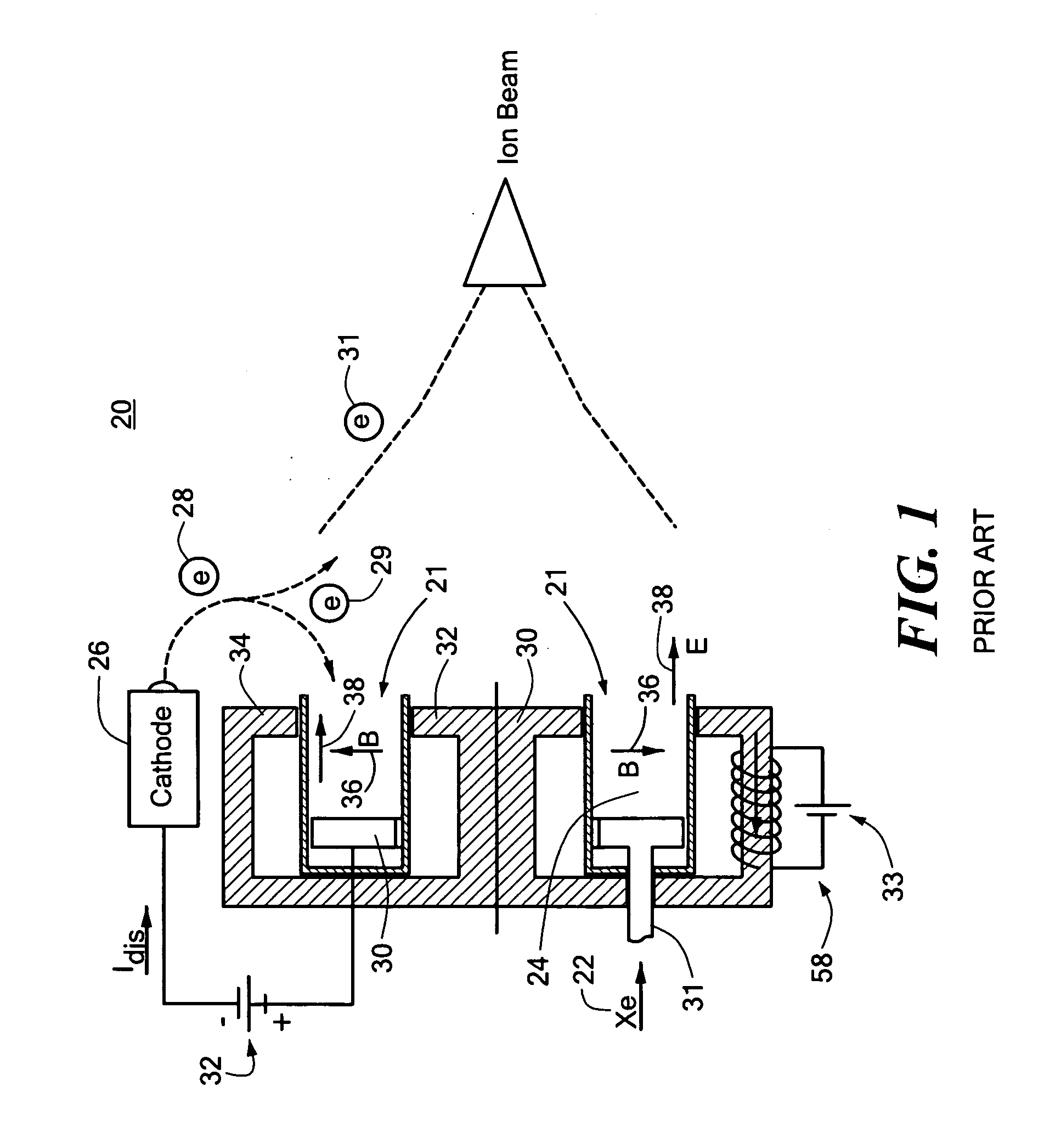
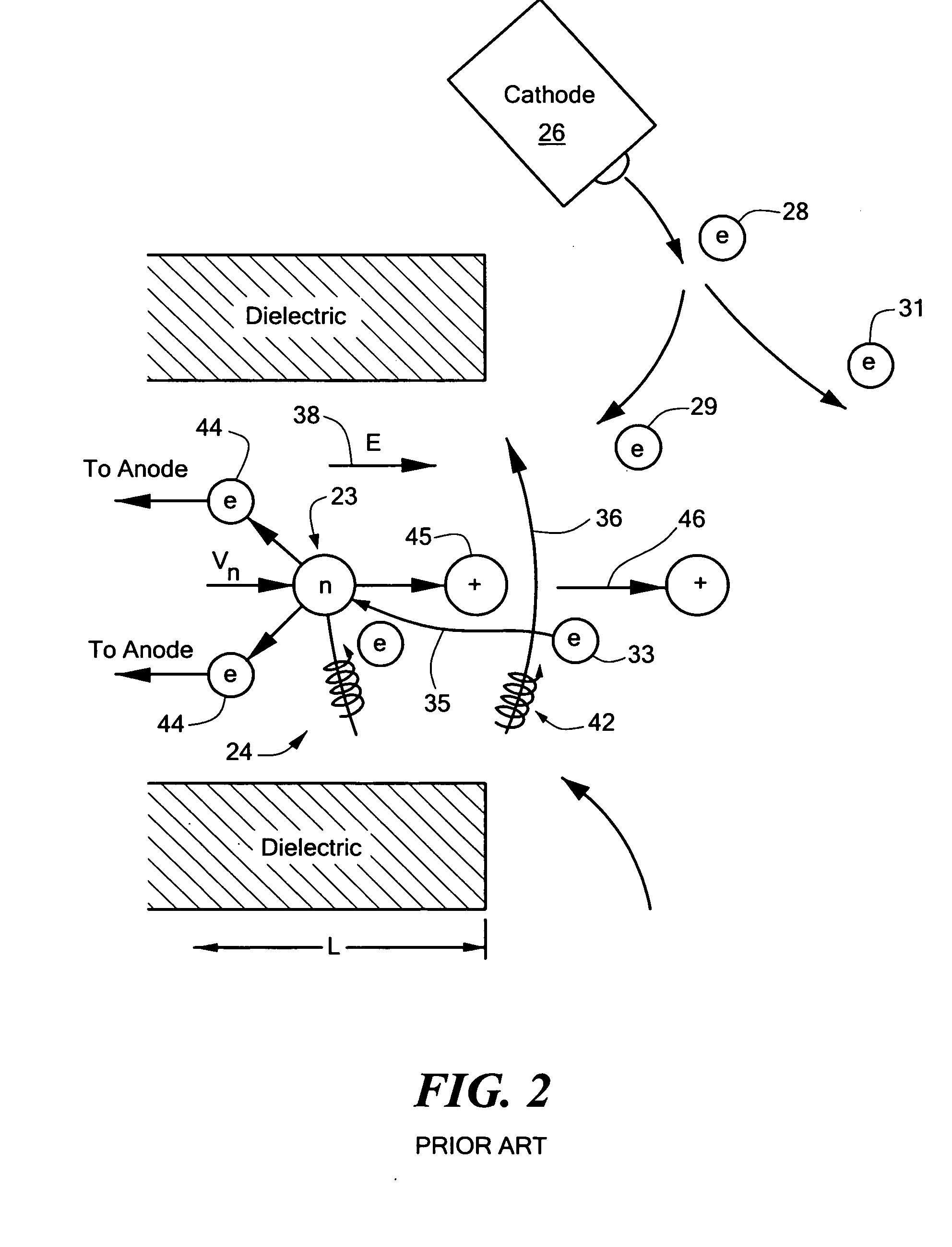
[0044] A typical conventional Hall effect thruster 20, FIG. 1, includes plasma accelerator 21 with discharge chamber 24, anode 30 and propellant distributor 31 in discharge chamber 24 with transverse magnetic field 36 and axial electric field 38. Propellant 22, e.g., xenon or similar gas, is introduced through propellant ...
PUM
 Abstract
Description
Claims
Application Information