Servo control device and method of adjusting servo system

a servo control device and servo system technology, applied in the field of numerical control devices, can solve the problems of reducing the work efficiency of adjusting the single control axis, affecting so as to achieve the effect of reducing the adjustment cost and increasing the efficiency of adjusting work

Active Publication Date: 2006-08-24
FANUC LTD
View PDF8 Cites 8 Cited by
  • Summary
  • Abstract
  • Description
  • Claims
  • Application Information

AI Technical Summary

Benefits of technology

[0016] According to the present invention, a sine arc instruction is given to the servo system as a move instruction having periodicity. Position feedback data and data before one quarter cycle or after one quarter cycle or position data based on the position instruction before one quarter cycle or after one quarter cycle are converted into each position data of the X-axis and the Y-axis, and an image obtained is drawn on the two-dimensional plane (X-Y plane). This has the same effect as that of drawing a track of the obtained position feedback data, based on the arc instruction to the orthogonal two axes. Accordingly, it becomes possible to visually adjust the servo system of a single control axis such as a straight line axis and a rotation axis having no adjacent orthogonal axes.
[0017] Consequently, in the servo system of a single control axis such as a straight line axis and a rotation axis having no adjacent orthogonal axes, it becomes possible to carry out a high-precision evaluation of the machine tool without actually executing a work process. As a result, efficiency of the adjusting work can be increased, and adjustment cost can be decreased.

Problems solved by technology

At the time of adjusting a servo system of a single control axis such as a straight line axis and a rotation axis having no adjacent orthogonal axes, a shape error also occurs before and after the speed polarity is changed.
Therefore, the servo system cannot be visually adjusted easily.
When this method is used, the work efficiency of adjusting the single control axis such as a straight line axis and a rotation axis having no adjacent orthogonal axes is extremely decreased, and the adjustment cost increases substantially.

Method used


Image

  • Servo control device and method of adjusting servo system
  • Servo control device and method of adjusting servo system
  • Servo control device and method of adjusting servo system

Examples


first embodiment

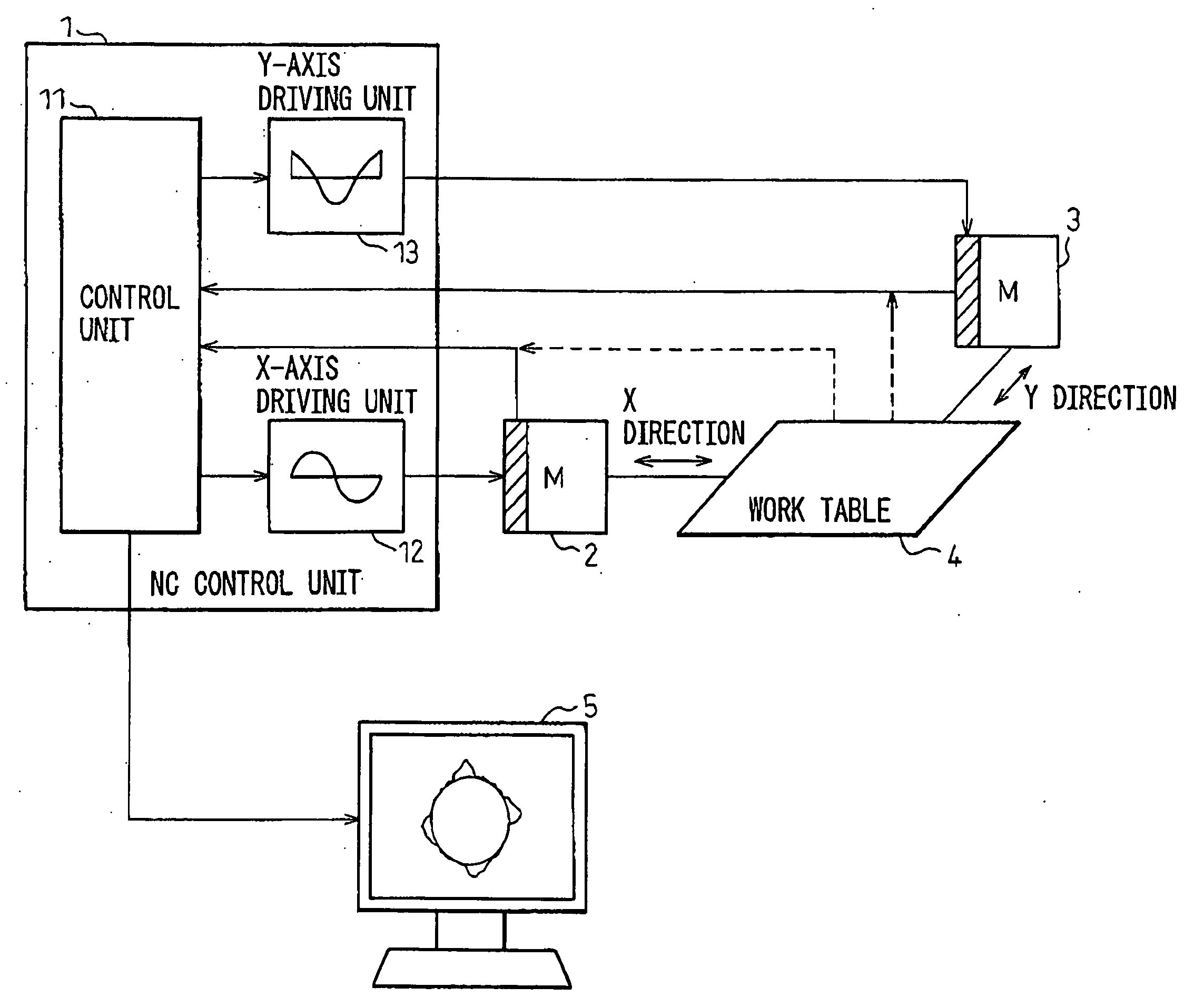
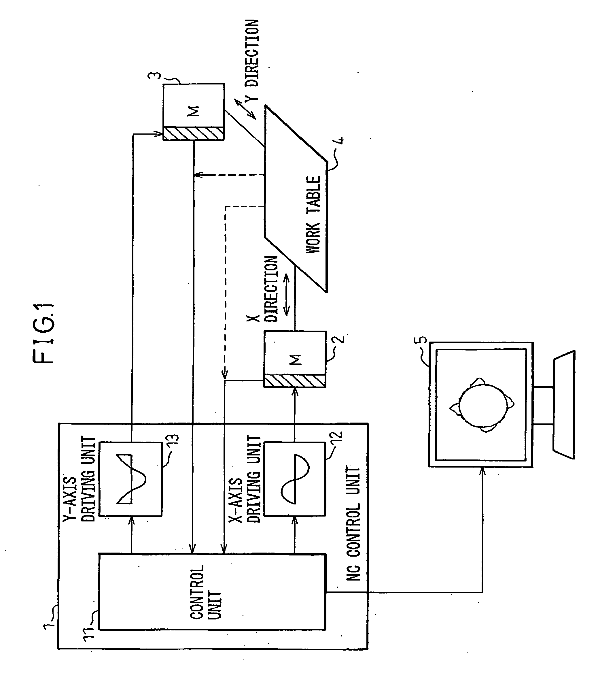
[0035]FIG. 5 shows a configuration of a servo control system according to the present invention.

[0036] In FIG. 5, a control unit 50 is configured by a central processing unit (CPU) circuit. During the operation, the control unit 50 refers to a parameter table 51 disposed on a random access memory (RAM), obtains move speed / current data of a servo motor 54 corresponding to the position data of an arc instruction (x=sin θ) in one direction, and gives the move speed / current data to an X-axis driving unit 53. With this arrangement, the servo motor 54 is driven, and position data, such as a rotation number / angle and a move position that are output from a pulse coder not shown inside the servo motor 54 and a linear scale not shown fitted to a work table 55, is fed back to the control unit 50.

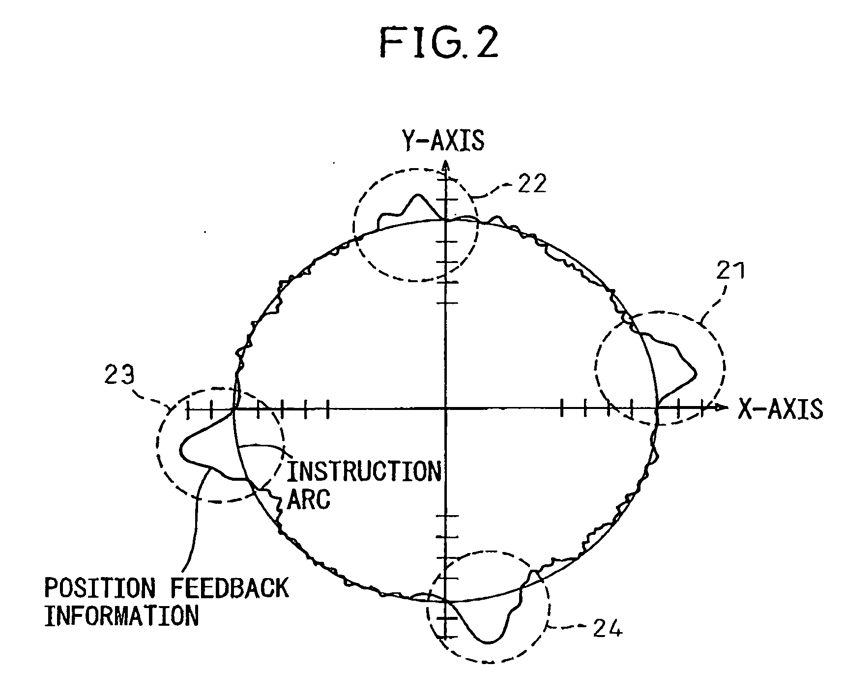
[0037] The control unit 50 receives the position feedback data, and compares the position feedback data with the position data that the control unit 50 has given to the X-axis driving unit 53, and obt...

second embodiment

[0044]FIG. 8 shows a configuration of a servo control system according to the present invention.

[0045] According to the present embodiment, a parameter table 61, an instruction data storage area 62, and a position data storage area 63 are provided by using a memory 60 incorporated in the CPU that constitutes the control unit 50 within the NC device. The parameter table 61 corresponds to the parameter table shown in FIG. 5. In the present embodiment, arc instruction data output from the X-axis driving unit 53 are sequentially stored in the instruction data storage area 62. Corresponding position feedback data from the servo system are sequentially stored in the position data storage area 63.

[0046] The control unit 50 receives the position feedback data from the position data storage area 63, and converts the position feedback data into X-axis position data (x=α sin θ, α=1+Δ (θ)). The controller 50 obtains arc instruction data of which phase is different by 90 degrees, from the instr...


PUM


Abstract

The invention relates to a numerical control (NC) device, and provides a servo control device that displays, by a two-dimensional image, evaluation of control precision of a servo system, and that can adjust the servo system according to a visual method, and provides a method of adjusting the servo system. The control device includes: an instruction unit that instructs a position instruction having periodicity; a unit that records a track of position data based on a position feedback of a servo system according to the position instruction; and a first drawing unit that draws position data based on the position feedback, data before a quarter cycle or after a quarter cycle of the position data or position data based on the position instruction before a quarter cycle or after a quarter cycle, on a two-dimensional plane including orthogonal two axes, as the axis data of the orthogonal two axes respectively.

Description

RELATED APPLICATIONS [0001] The present application is based on, and claims priority from, Japanese Application Number 2005-040582, filed Feb. 17, 2005, the disclosure of which is hereby incorporated by reference herein in its entirety. FIELD OF THE INVENTION [0002] The present invention relates to a numerical control (NC) device. Particularly, the invention relates to an adjusting device that adjusts the control precision of a servo system, and a method of adjusting the servo system. BACKGROUND OF THE INVENTION [0003] Conventionally, a machine having plural axes, such as an NC machine tool, gives an arc instruction as orthogonal straight lines having two axes, draws position feedback data of the straight lines having two axes on a two-dimensional plane, and adjusts a servo system using a shape of this track as an evaluation reference, as disclosed in Japanese Patent Application Unexamined Publication No. 4-177408 and Japanese Patent Application Unexamined Publication No. 2002-12012...

Claims


Application Information

Patent Timeline
Patent Type & Authority Applications(United States)
IPC IPC(8): G05B19/33
CPCG05B19/406G05B2219/35292G05B2219/35338G05B2219/37078G05B2219/37619
Inventor IWASHITA, YASUSUKEAKIYAMA, TAKAHIRONIWA, MASAKAZU
Owner FANUC LTD
Why Eureka
Try Eureka