Delta-sigma modulator and its application to switching amplification circuit

a modulator and delta-sigma technology, applied in the field of switching amplification circuits, can solve the problems of high rate, achieve high output power, high oscillation threshold value, and high power efficiency

Inactive Publication Date: 2006-08-24
SHARP KK
View PDF9 Cites 29 Cited by
  • Summary
  • Abstract
  • Description
  • Claims
  • Application Information

AI Technical Summary

Benefits of technology

[0013] The present invention has been made in view of the foregoing problems, and has an object to provide: a delta-sigma modulator allowing realization of both (i) a high oscillation threshold value, i.e., high output power, and (ii) high power efficiency; and a switching amplification circuit using the delta-sigma modulator.

Problems solved by technology

Further, the average switching rate is high when the loop delay amount is small, and decreases as the loop delay amount is increased.

Method used


Image

  • Delta-sigma modulator and its application to switching amplification circuit
  • Delta-sigma modulator and its application to switching amplification circuit
  • Delta-sigma modulator and its application to switching amplification circuit

Examples


first embodiment

[0046] One embodiment of the present invention will be described below with reference to FIGS. 1 to 11.

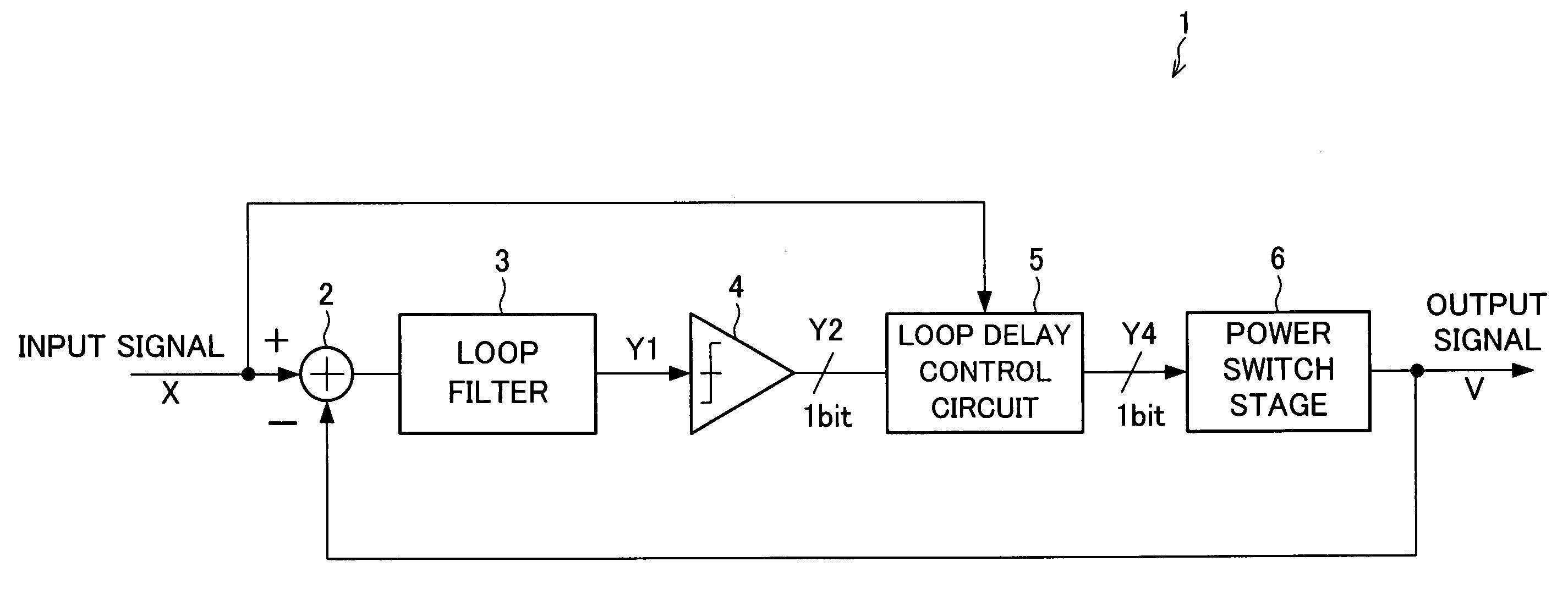
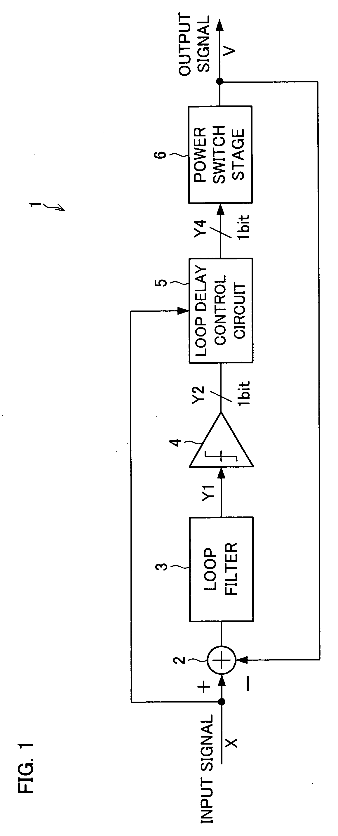
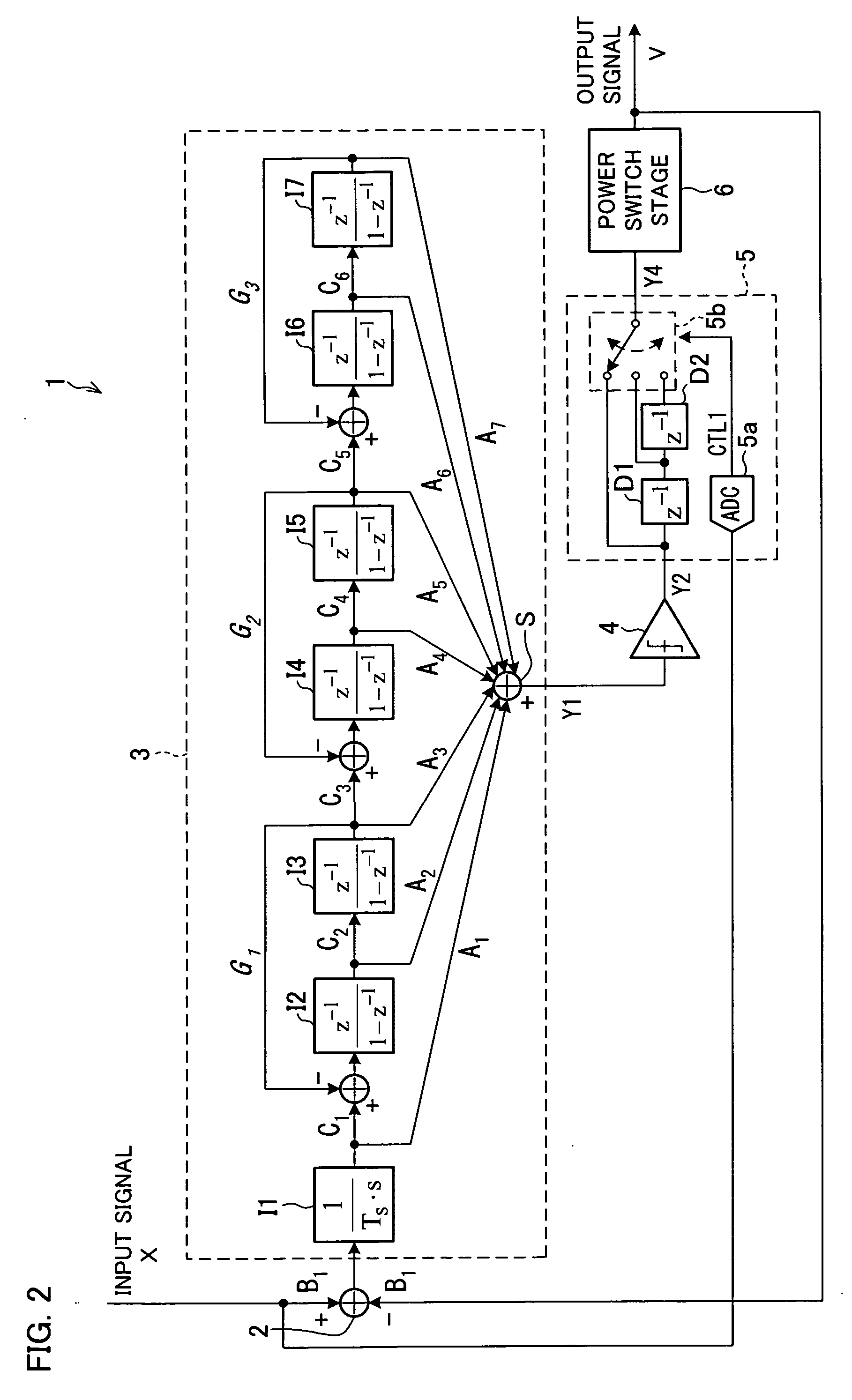
[0047]FIG. 1 illustrates an arrangement of a switching amplification circuit 1 according to the present embodiment. The switching amplification circuit 1 includes a subtracter 2, a loop filter 3, a comparator 4, a loop delay control circuit 5, and a power switch stage 6. The subtracter 2 calculates a difference between (i) an input signal X supplied to the switching amplification circuit 1 and (ii) an output signal V supplied from the switching amplification circuit 1. The loop filter 3 integrates a signal supplied from the subtracter 2. The comparator 4 converts an output signal Y1 of the loop filter 3 into a 1-bit signal, and outputs the 1-bit signal as an output signal Y2. The loop delay control circuit 5 delays the output signal Y2 of the comparator 4 in accordance with the amplitude of the input signal X, and outputs the delayed signal as an output signal Y4. The power switch...

second embodiment

[0074] Another embodiment of the present invention will be described below with reference to FIGS. 12 to 18.

[0075]FIG. 12 illustrates an arrangement of a switching amplification circuit 11 according to the present embodiment. The switching amplification circuit 11 includes a subtracter 12, a loop filter 13, a comparator 14, a pulse width control circuit 15, and a power switch stage 16. The subtracter 12 calculates a difference between (i) an input signal X supplied to the switching amplification circuit 11 and (ii) an output signal V supplied from the switching amplification circuit 11. The loop filter 13 integrates a signal supplied from the subtracter 12, and outputs the integrated signal as an output signal Y1. The comparator 14 converts the output signal Y1 of the loop filter 13 into a 1-bit signal, and outputs the 1-bit signal as an output signal Y2. The pulse width control circuit 15 changes, in accordance with the input signal X, a minimum pulse width of the output signal Y2...


PUM


Abstract

A loop delay control circuit is provided between a comparator and a power switch stage. When the amplitude of an input signal is especially high, the loop delay control circuit secures an oscillation threshold value by setting a delay amount at a low value. On the other hand, when the amplitude of the input signal is not so high, the loop delay control circuit reduces an average switching rate by increasing the delay amount, but does not reduce the oscillation threshold value. This makes it possible to provide a delta-sigma modulator allowing realization of both (i) a high oscillation threshold value, i.e., high output power, and (ii) high power efficiency.

Description

[0001] This Nonprovisional application claims priority under 35 U.S.C. § 119(a) on Patent Application No. 043218 / 2005 filed in Japan on Feb. 18, 2005, the entire contents of which are hereby incorporated by reference. FIELD OF THE INVENTION [0002] The present invention relates to (i) a delta-sigma (ΔΣ) modulator and (ii) a switching amplification circuit using the delta-sigma modulator. Particularly, the present invention relates to an improvement in performance of a modulation circuit controlling a switching element. BACKGROUND OF THE INVENTION [0003] A switching amplification circuit is known as a class-D amplifier, and allows for high-efficiency amplification of an input signal when used together with a PWM modulation circuit, a synchronous delta-sigma modulation circuit, and an asynchronous delta-sigma modulation circuit. A switching amplification circuit using a delta-sigma modulator is disclosed in Non-patent Document 1 (“A delta-sigma modulator for 1-bit digital switching amp...

Claims


Application Information

Patent Timeline
Patent Type & Authority Applications(United States)
IPC IPC(8): H03M3/00
CPCH03M3/366H03M3/43H03M3/448H03M3/452H03M3/506
Inventor FUJIMOTO, YOSHIHISA
Owner SHARP KK
Why Eureka
Try Eureka