Magnetic head with a slider and a gimbal suspension structuring flexure

a technology of gimbal and slider, which is applied in the direction of maintaining the head carrier alignment, recording information storage, instruments, etc., can solve the problems of significant change in the flatness of the recording medium-opposed surface of the slider, and achieve the reduction of slider deformation and bonding strength. , the effect of improving the bonding strength

Active Publication Date: 2006-08-24
TDK CORPARATION
View PDF10 Cites 7 Cited by
  • Summary
  • Abstract
  • Description
  • Claims
  • Application Information

AI Technical Summary

Benefits of technology

[0012] A contact surface area of the adhesive agent is reduced from the portion closer to the end surfaces of the spacer projections on the trailing side toward an end surfaces on a leading side. In this structure, deformation of the slider in association with change in temperature at the time of curing the adhesive agent can be reduced, and the bonding surface area can be secured to improve the bonding strength.
[0013] Preferably, fillets are formed between opposing side surfaces of the slider in the vicinity of the end surface on the trailing side and the surface opposing to the flexure, and the slider and the flexure are bonded by an adhesive agent filled between the respective fillets and the flexures. With these fillets, the bonding surface area is secured, and deformation of the slider can be reduced, and also the bonding strength can be secured.
[0014] Since the distance between the ball bonding portion on the end surface of the slider on the trailing side and the bonding portion is short, even when the flexure and the slider are expanded and contracted at different coefficients of thermal expansion due to change in temperature, the influence of the difference of expansion and contraction is small and hence the amount of deformation of the recording-medium-opposed surface of the slider is small.

Problems solved by technology

There is also a problem such that the flatness of the recording-medium-opposed surface of the slider is significantly changed due to expansion or contraction of the flexure due to change in temperature of operating environment in a state of being assembled in a hard disk device.

Method used


Image

  • Magnetic head with a slider and a gimbal suspension structuring flexure
  • Magnetic head with a slider and a gimbal suspension structuring flexure
  • Magnetic head with a slider and a gimbal suspension structuring flexure

Examples


Embodiment Construction

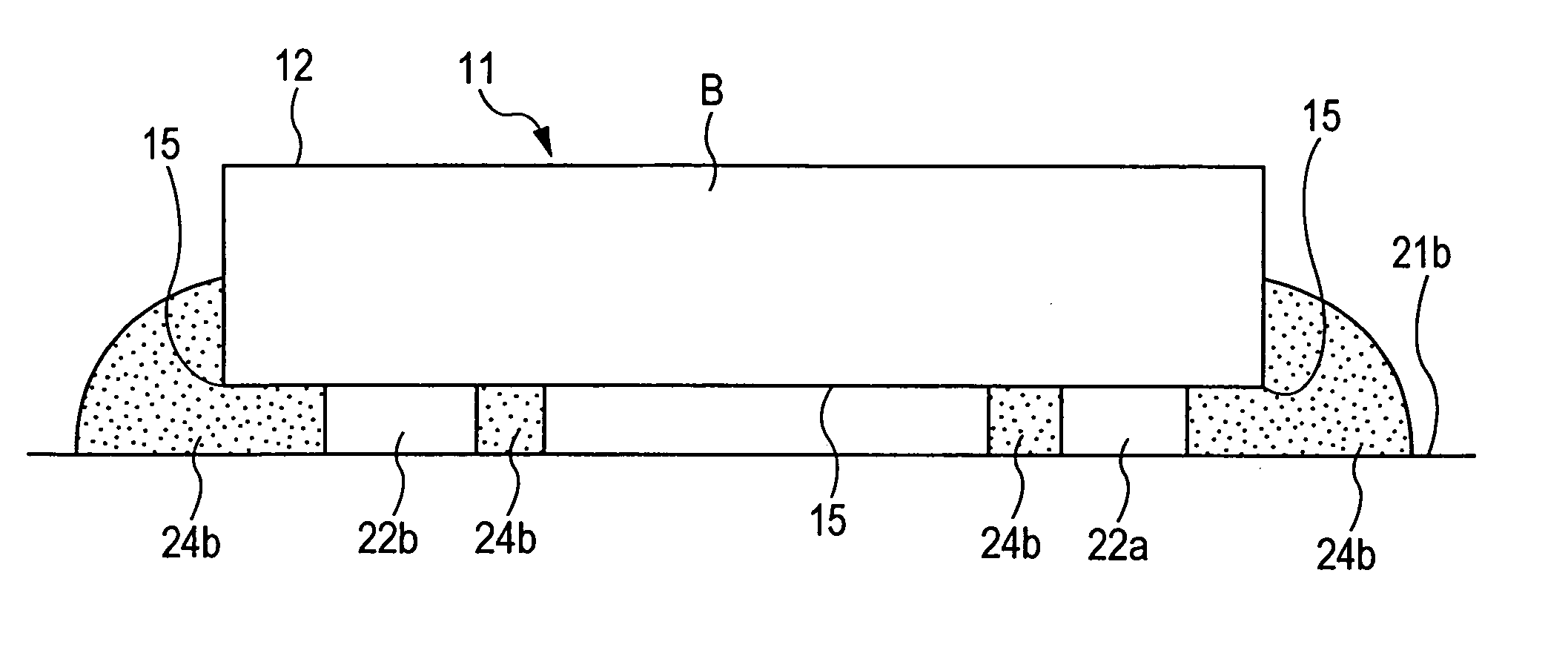
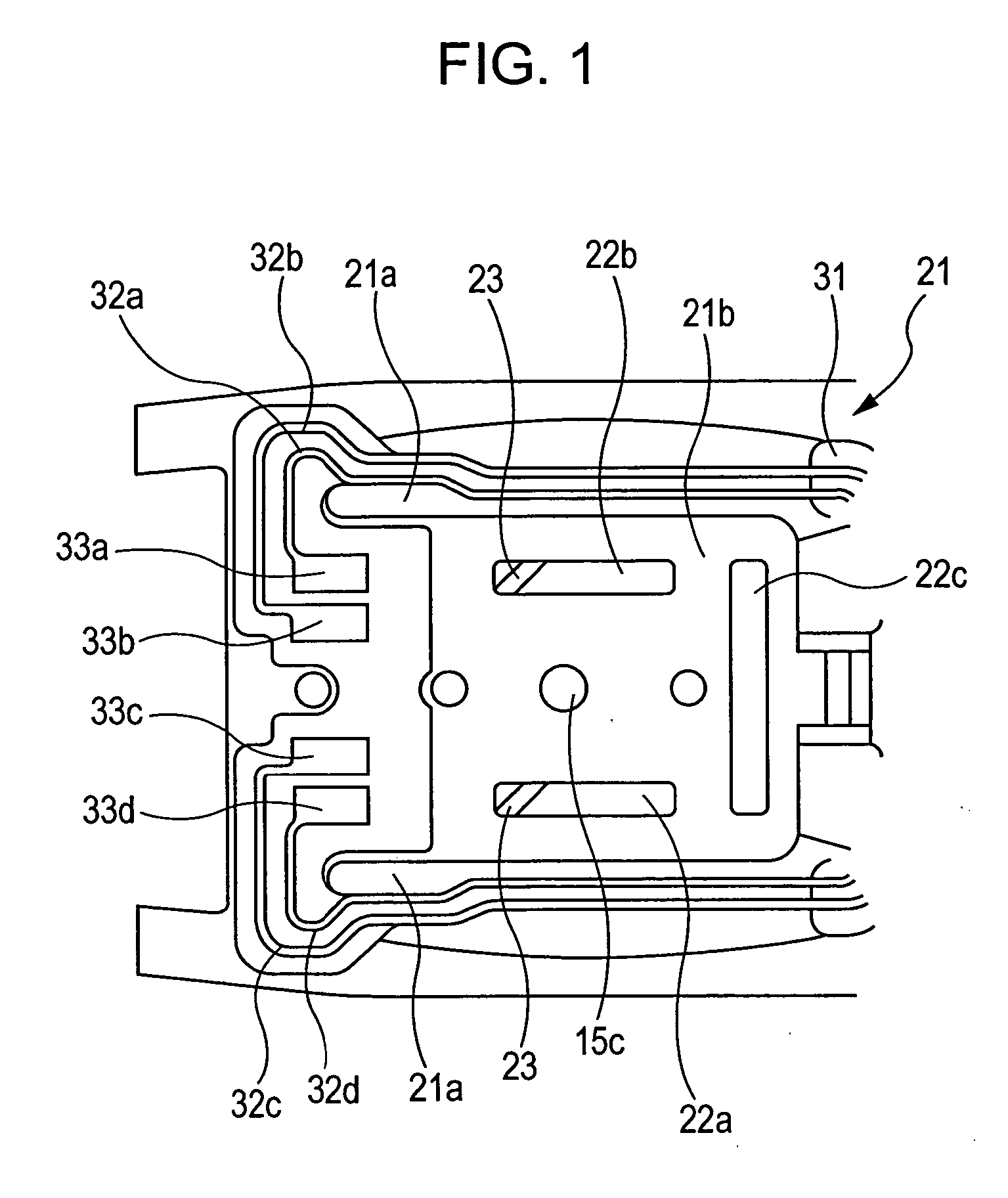
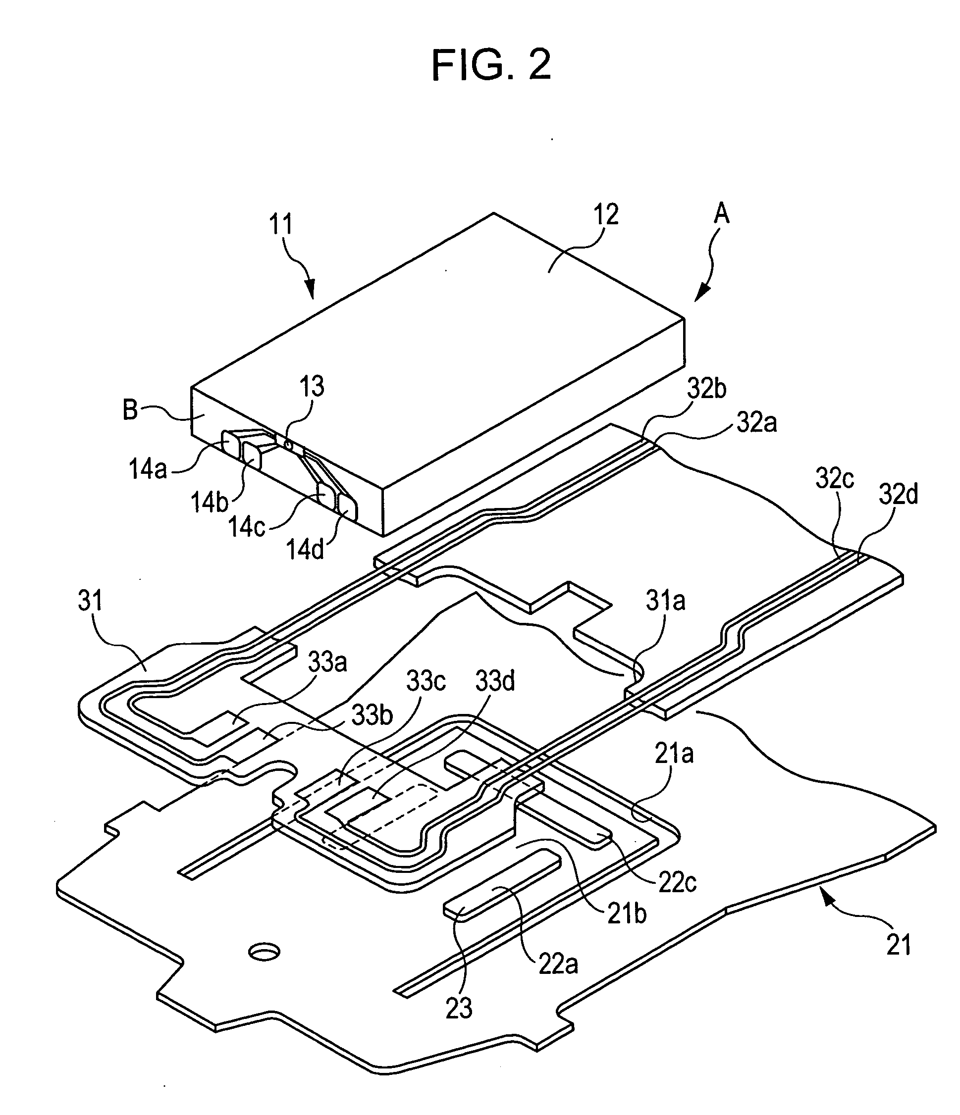
[0025]FIG. 1 is a plan view of a distal end portion of a flexure 21 which constitutes a head gimbal assembly according to an embodiment to which the invention is applied; FIG. 2 is an exploded perspective view of a flexure portion. The flexure 21 is formed of stainless steel welded by a laser beam to a distal end portion of a load beam which is rotatably supported on a revolving shaft, not shown.

[0026] A slider bonding tongue 21b which is resiliently deformable by a U-shaped through groove 21a is formed at a distal end portion of the flexure 21. An FPC substrate 31 is provided on the flexure 21 so as to surround the U-shaped through groove 21a. In FIG. 2, although the FPC substrate 31 is shown as a separate member from the flexure 21 for the sake of convenience, the FPC substrate 31 is actually formed by laminating a resin base and a lead on the flexure 21. The slider bonding tongue 21b is exposed from a hole 31a on the FPC substrate 31.

[0027] The FPC substrate 31 is formed with l...


PUM

PropertyMeasurementUnit
areaaaaaaaaaaa
contact surface areaaaaaaaaaaa
lengthaaaaaaaaaa

Abstract

A magnetic head is provided that is formed by fixedly bonding a slider having a thin-film magnetic element on a flexure formed of metallic material which constitutes a gimbal suspension. The slider includes electrodes conducted to the thin-film magnetic head on an end surface thereof on a trailing side which is orthogonal to the recording-medium-opposed surface. The flexure has independent spacer projections. The slider and the flexure are bonded by an adhesive agent applied to bonding areas on end surfaces of a pair of spacer projections positioned in the vicinity of the end surface on the trailing side out of the spacer projections.

Description

BACKGROUND OF THE INVENTION [0001] 1. Field of the Invention [0002] The present invention relates to a magnetic head and, more specifically, to a magnetic head having a bonding structure between a slider and a flexure of a head gimbal assembly for supporting the slider. [0003] 2. Description of the Related Art [0004] An HGA (head gimbal assembly) which is widely used in HDD is formed by fixedly bonding a slider having a thin-film magnetic head element (MR element, GMR element) on one end portion of a flexure formed of metallic material which is fixed to a distal end of a load beam. In the related art, a spacer projection is fixed to a surface of the flexure, and the slider is bonded in an area surrounded by the spacer projection where adhesive agent is applied (Japanese Unexamined Patent Application Publication No. 9-282824 (U.S. Pat. No. 5,880,908), Japanese Unexamined Patent Application Publication No. 10-27447, and Japanese Unexamined Patent Application Publication No. 11-39627)....

Claims


Application Information

Patent Timeline
Patent Type & Authority Applications(United States)
IPC IPC(8): G11B5/60
CPCG11B5/4826
Inventor WATANABE, MITSURU
Owner TDK CORPARATION
Why Eureka
Try Eureka