Motion vector detecting device

a detection device and motion vector technology, applied in the field of motion vector detection technique, can solve the problems of increasing the amount of data transmitted, reducing the processing speed of compression coding, and affecting the efficiency of coding processing, so as to reduce the time needed and improve the processing efficiency

Active Publication Date: 2006-08-24
GK BRIDGE 1
View PDF7 Cites 25 Cited by
  • Summary
  • Abstract
  • Description
  • Claims
  • Application Information

AI Technical Summary

Benefits of technology

[0009] The present invention has been made in view of the aforementioned problems. Accordingly, it is an object thereof to provide a coding techn...

Problems solved by technology

Accordingly, the demand for memory bandwidth can easily lead to a bottleneck in the processing.
This requires a great number of readouts from the frame memory, increasing the data transmission amount.
As a result, access to the frame memory be...

Method used


Image

  • Motion vector detecting device
  • Motion vector detecting device
  • Motion vector detecting device

Examples


first embodiment

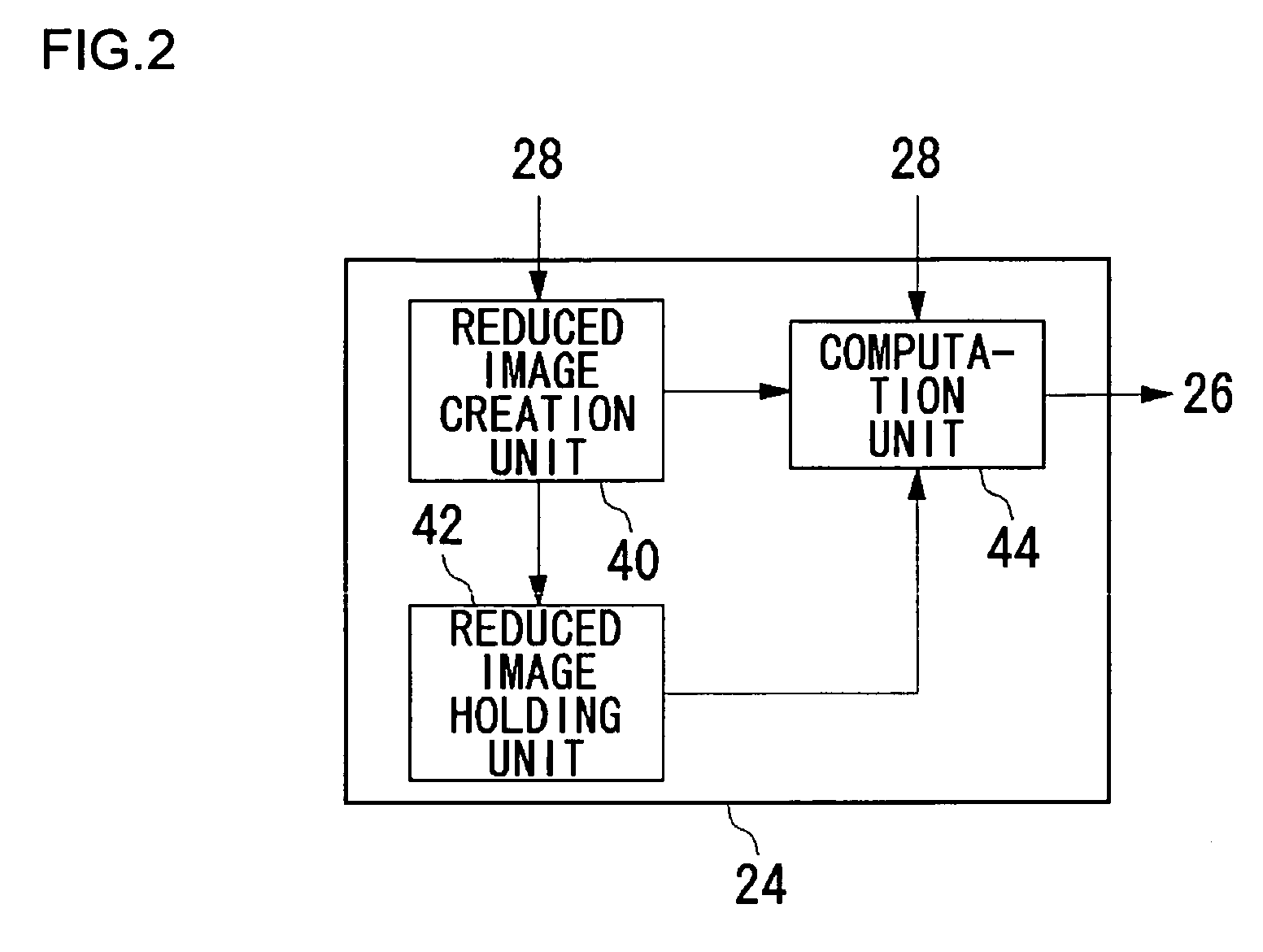
[0032] With an image coding device according to an embodiment of the present invention, first, a reduced image at a reduced resolution is created based upon an image which is to be coded. Then, a rough motion vector (which will be referred to as “approximate motion vector” hereafter) at a low resolution is detected based upon the reduced image. Subsequently, the motion vector is detected based upon the original image at a high resolution with reference to the approximate motion vector. The present invention offers a technique which can be applied to such a hierarchical motion vector detection method, and which improves the motion vector detection speed while reducing the memory access amount.

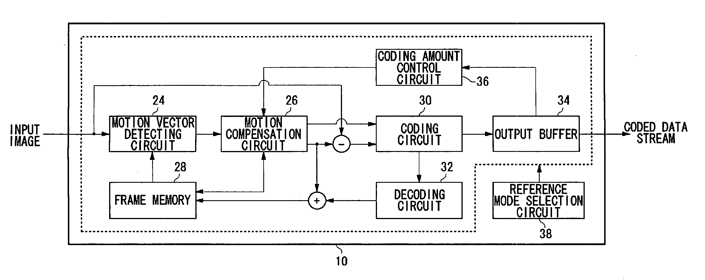
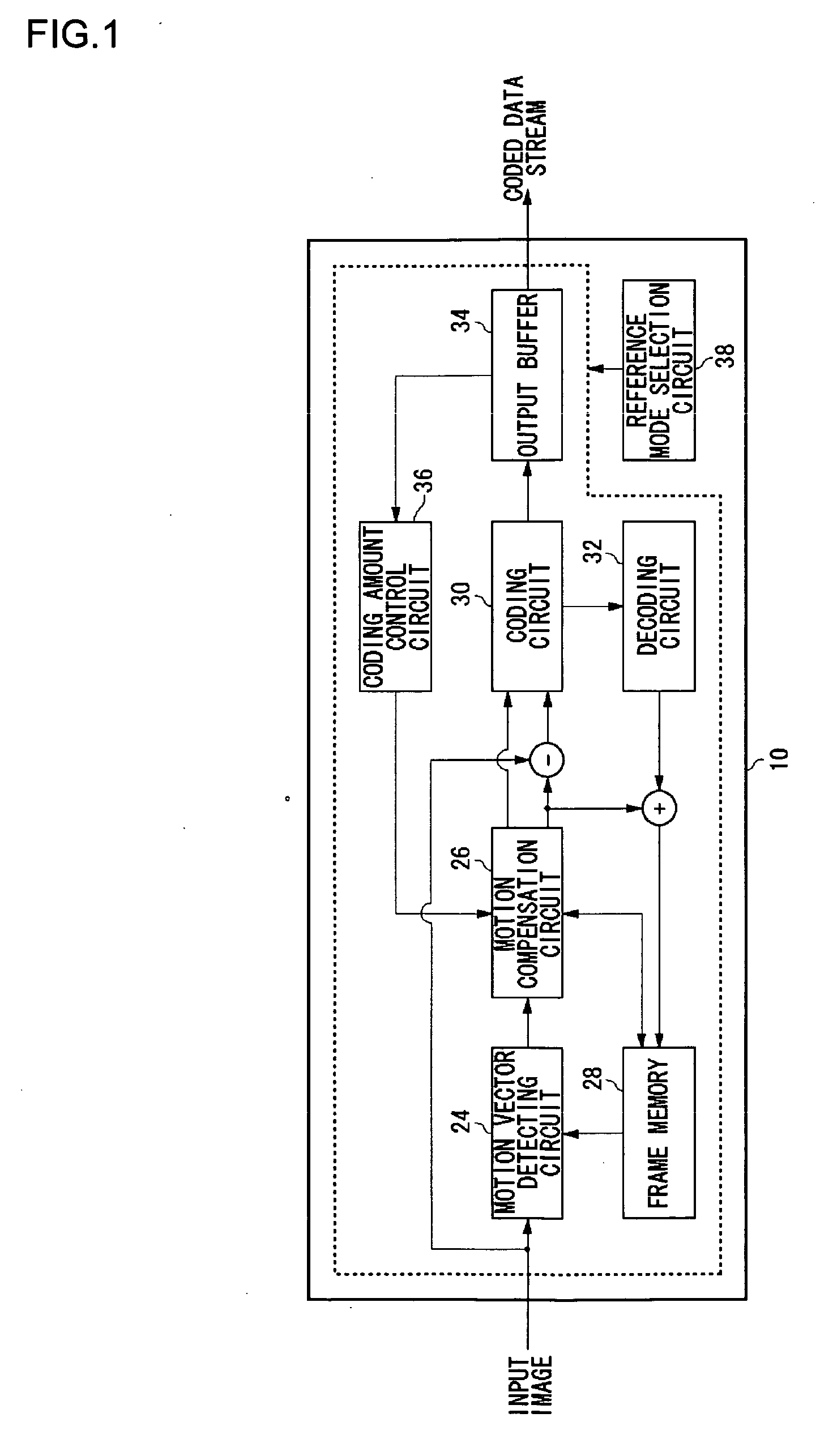
[0033]FIG. 1 shows an overall configuration of an image coding device 10 according to an embodiment of the present invention. The image coding device 10 includes a motion vector detecting circuit 24, a motion compensation circuit 26, frame memory 28, a coding circuit 30, a decoding circuit 32, ...

second embodiment

[0059]FIG. 7 is a configuration diagram which shows a coding device 100 according to an embodiment. This configuration can be realized by hardware means, e.g., by actions of a CPU, memory, and other LSIs, of a computer, or by software means, e.g., by actions of a program having a function of image coding or the like, loaded into the memory. Here, the drawing shows a functional block configuration which is realized by cooperation between the hardware components and software components. It is needless to say that such a functional block configuration can be realized by hardware components alone, software components alone, or various combinations thereof, which can be readily conceived by those skilled in this art.

[0060] The coding device 100 according to the present embodiment performs coding of motion images stipulated by: the MPEG series standard, which is a member of the ISO / IEC family of standards; the H.26x series standard, which is a member of the ITU-T family of standards; or ...


PUM


Abstract

A motion vector detecting unit 24 detects a motion vector between an input image and a reference image. A reduced image creation unit 40 reads out pixel data of the reference image from the frame memory, and creates a reduced image at a lower resolution than that of the original reference image. A reduced image holding unit 42 stores a part or all of the reduced image thus created. A computation unit 44 performs matching computation between the input image and the reference image using the reduced images, thereby detecting an approximate motion vector. Subsequently, the computation unit 44 detects a motion vector using the images at the original resolution with reference to the approximate motion vector. When the computation unit 44 detects the motion vector using the reduced images, a part of the reduced image stored in the reduced image holding unit 42 is not newly created, and is read out from the reduced image holding unit 42.

Description

BACKGROUND OF THE INVENTION [0001] 1. Field of the Invention [0002] The present invention relates to a motion vector detection technique, e.g., a device having a function for detecting an interframe motion vector for coding motion images with an image coding method including an interframe prediction mode. [0003] 2. Description of the Related Art [0004] The rapid development of the broadband network has increased consumer expectations for the service that provide high-quality motion images. On the other hand, large capacity storage media such as DVD and so forth are used for storing high-quality motion images. This increases the segment of the users who enjoy high-quality images. A compression coding method is an indispensable technique for transmission of motion images via a communication line, and storing the motion images in a storage medium. Examples of international standards of motion image compression coding techniques include the MPEG-4 standard, and the H.264 / AVC standard. F...

Claims


Application Information

Patent Timeline
IPC IPC(8): H04N11/02H04N11/04H04N7/12H04B1/66
CPCG06T7/2073H04N19/105H04N19/53H04N19/433H04N19/152G06T7/207
Inventor SUZUKI, MITSURUOKADA, SHIGEYUKI
Owner GK BRIDGE 1
Why Eureka
Try Eureka