Image processing apparatus, image processing method, and distortion correcting method

a distortion correction and image processing technology, applied in the field of distortion correction methods, can solve the problems of data unused/data shortage portion of corrected images, and achieve the effect of without increasing the amount of transfer data through the bus or the memory capacity, and preventing the overwriting of the region

Active Publication Date: 2006-08-24
OLYMPUS CORP
View PDF11 Cites 66 Cited by
  • Summary
  • Abstract
  • Description
  • Claims
  • Application Information

AI Technical Summary

Benefits of technology

[0054] With the configuration, the data is written and read to/from the memory unit in units of UL. Thus, it is sufficient to provide the buffer capacity of the memory unit corresponding to at least the capacity corresponding to one UL. The distortion can be corrected without increasing the amount of transfer data through the bus or the capacity of memory.
[0055] Further, preferably, the memory control unit has areas (preULB and postULB) wi...

Problems solved by technology

However, in the distortion correction using [Formula 5] optically...

Method used


Image

  • Image processing apparatus, image processing method, and distortion correcting method
  • Image processing apparatus, image processing method, and distortion correcting method
  • Image processing apparatus, image processing method, and distortion correcting method

Examples


first embodiment

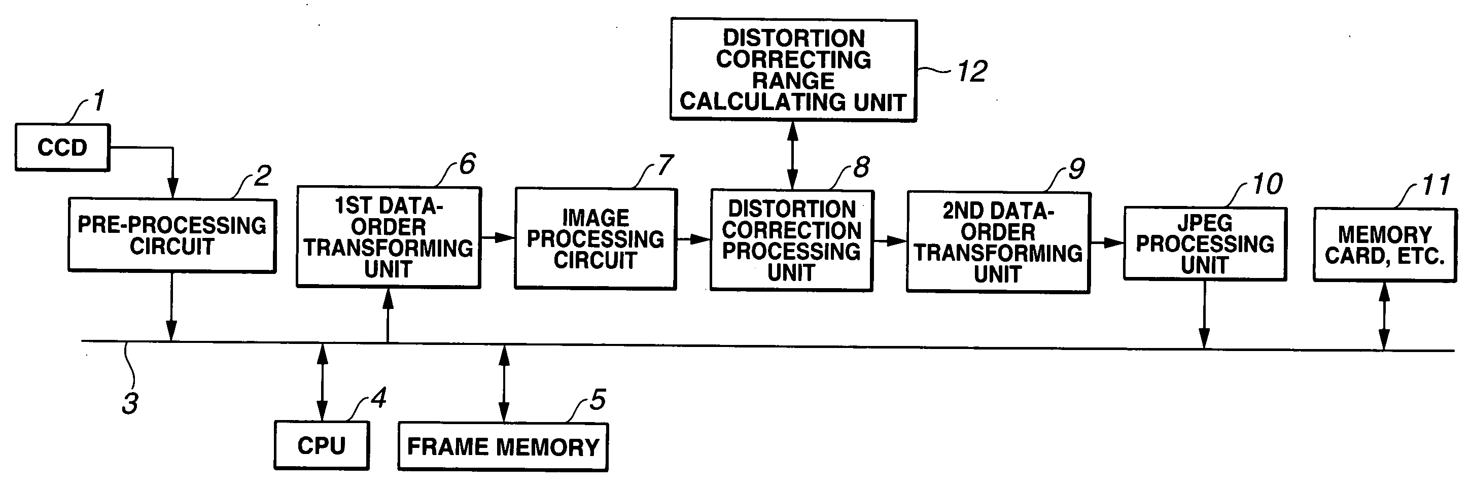
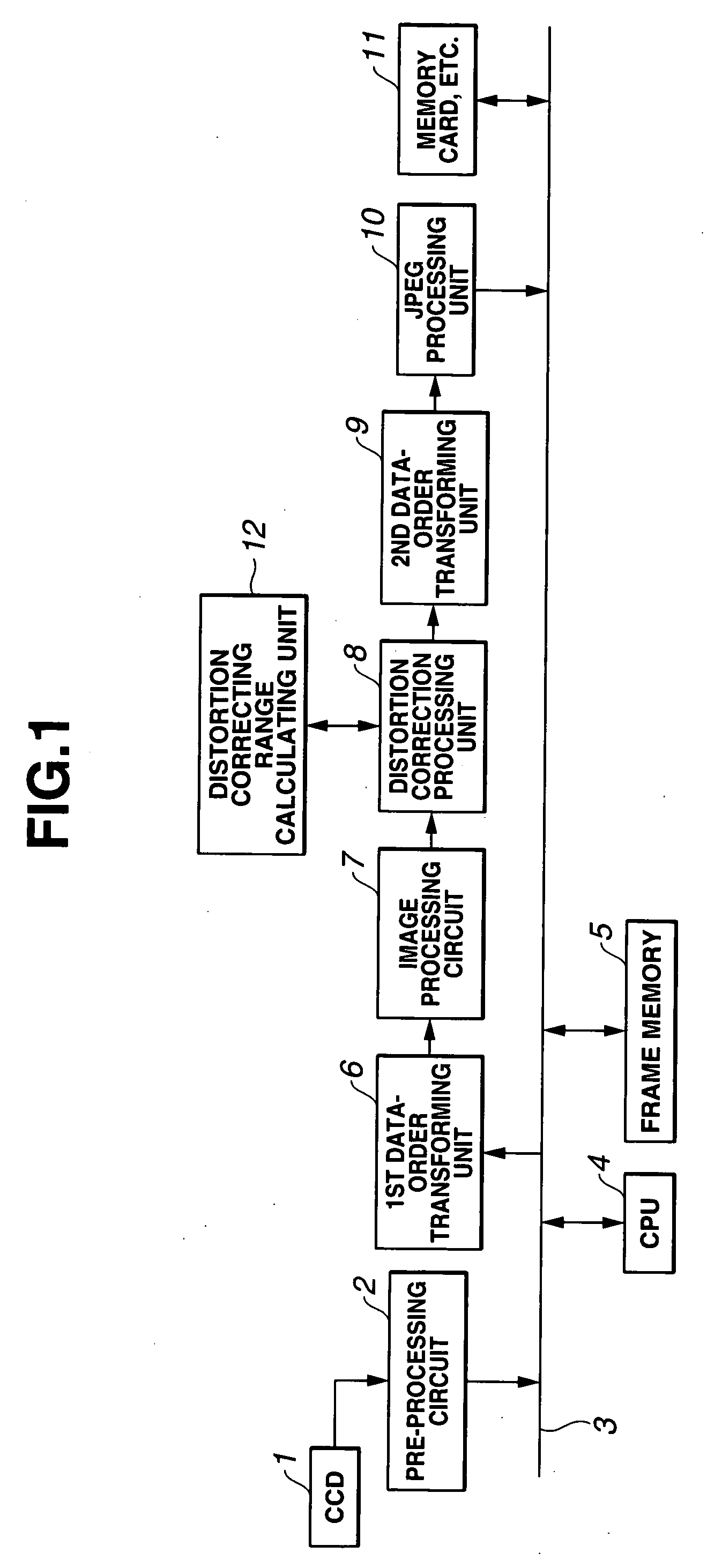
[0115]FIG. 1 is a block diagram showing the entire configuration of an image processing apparatus according to the present invention.

[0116] In the image processing apparatus shown FIG. 1, an image pickup signal from a CCD 1 is subjected to pixel defect processing and A / D conversion by a pre-processing circuit 2 under the control of a CPU 4 which controls units connected to a bus 3. The obtained image data is temporarily stored in a frame memory 5 via the bus 3. The frame memory 5 comprises an SDRAM and the like, and stores data before image processing and data after the image processing. Subsequently, the image data read from the frame memory 5 is inputted to a first data-order transforming unit 6 via the bus 3. The first data-order transforming unit 6 comprises a plurality of memories, here, two, which can store data in units of block, as will be described later with reference to FIG. 7. The first data-order transforming unit 6 sequentially reads and stores the data in the row dire...

second embodiment

[0175]FIG. 21 is a block diagram showing the entire configuration of an image processing apparatus according to the present invention. The configuration shown in FIG. 21 is obtained by deleting the distortion correcting range calculating unit 12 shown in FIG. 1. The configuration of the distortion correction processing unit shown in FIG. 21 is the same as that shown in FIG. 2.

[0176] [Formula 1] in the coordinate transformation for distortion correction calculates the position on the entire screen of both the corrected image and the image at the position (X′, Y′) of a result of the coordinate transformation.

[0177] However, the image data inputted to the distortion correction processing unit 8 is in units of block line. The distortion correction processing unit 8 must know the spatial position relationship (position on the two-dimensional space) of the input image data. The control register 85 designates the position of the block line to be processed by the distortion correction proc...

third embodiment

[0216] The entire configuration of an image processing apparatus according to the present invention is the same as that shown in FIG. 21.

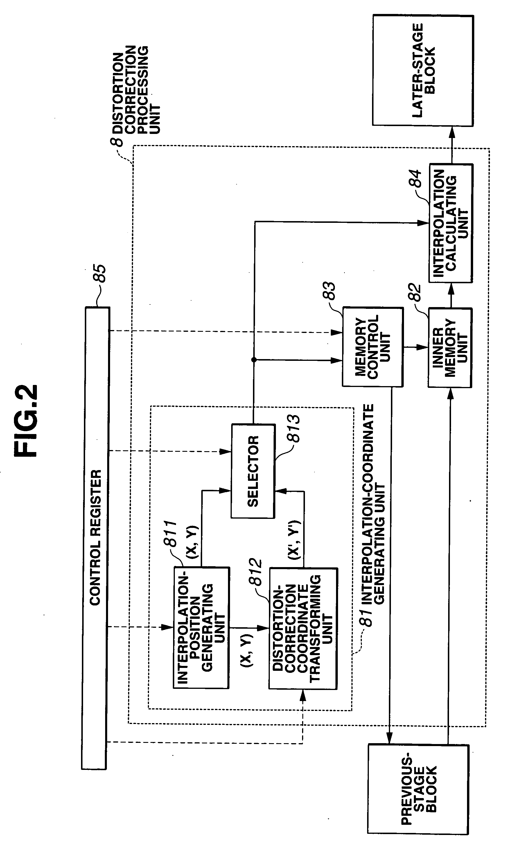
[0217]FIG. 37 shows the detailed configuration of the distortion correction processing unit 8 shown in FIG. 2.

[0218] A description is given of a corresponding relationship between units shown in FIG. 37 and the units shown in FIG. 2. Referring to FIG. 37, an interpolation-position calculating circuit 22 corresponds to the interpolation-position generating unit 811 shown in FIG. 2, a selector 24 corresponds to the selector 813 shown in FIG. 2, and a distortion-correction coefficient calculating circuit 21 and an interpolation-position correcting circuit 23 correspond to the distortion-correction coordinate transforming unit 812 shown in FIG. 2. Further, a 2-port SRAM 26 shown in FIG. 37 corresponds to the inner memory unit (inner buffer) 82 shown in FIG. 2. A write-address generating circuit 28, a buffer free capacity monitoring circuit 29, a data-...


PUM


Abstract

An image processing apparatus has a distortion correction processing unit. The image processing apparatus has a distortion correcting range calculating unit that calculates an input image range necessary for distortion correction processing of the distortion correction processing unit. Thus, the corrected image (output image) obtained by the distortion correction processing can be outputted without overs and shorts for the image output range. The distortion is corrected by effectively using input (picked-up) image data, serving as the original data. Further, the distortion including the pincushion distortion, the barrel distortion, and the curvilinear distortion is effectively corrected.

Description

CROSS REFERENCE TO RELATED APPLICATION [0001] This application is a continuation application of PCT / JP2004 / 011010 filed on Jul. 27, 2004 and claims benefit of Japanese Applications No. 2003-202493 filed in Japan on Jul. 28, 2003, No. 2003-202663 filed in Japan on Jul. 28, 2003, and No. 2003-202664 filed in Japan on Jul. 28, 2003, the entire contents of which are incorporated herein by this reference.BACKGROUND OF THE INVENTION [0002] 1. Field of the Invention [0003] The present invention mainly relates to an image processing apparatus and an image processing method used for an electronic image pickup device, such as a digital camera. In particular, the present invention relates to an image processing apparatus, an image processing method, and a distortion correcting method, in which a distortion correcting function is realized without increasing the circuit scale and the amount of transfer data and the spatial position of a small region can be calculated in the distortion correction...

Claims


Application Information

Patent Timeline
IPC IPC(8): G06K9/40G06T3/00G06T5/00H04N5/217
CPCG06T5/006H04N5/217G06T1/20H04N5/3572H04N23/81H04N25/61
Inventor HIGURASHI, MASAKIFURUKAWA, HIDEAKIUENO, AKIRA
Owner OLYMPUS CORP
Why Eureka
Try Eureka