Magnetic sensing element including free layer having gradient composition and method for manufacturing the same

a technology of gradient composition and magnetic sensing element, which is applied in the field of magnetic sensing element, can solve the problems of increasing and achieve the effect of reducing the asymmetry of reproduction waveform and high reproduction outpu

Active Publication Date: 2006-08-24
TDK CORPARATION
View PDF9 Cites 14 Cited by
  • Summary
  • Abstract
  • Description
  • Claims
  • Application Information

AI Technical Summary

Benefits of technology

[0071] In the present invention, the atomic percentage of the element Z, which is at least one element of Al, Sn, In, Sb, Ga, Si, Ge, Pb, and Zn, among the constituent elements of the above-described metal compound constituting the above-described free magnetic layer and the above-described pinned magnetic layer is decreased in a region close to the above-described non-magnetic material layer. Consequently, the ferromagnetic coupling magnetic field Hin due to the magnetostatic coupling (topological coupling) between the above-described free magnetic layer and the above-described pinned magnetic layer can be reduced.
[0072] Furthermore, in the above-described free magnetic layer or the above-described pinned magnetic layer, the atomic percentage of the above-described element Z is increased and a spin-dependent bulk scattering coefficient β is increased in a region at a distance from the above-described non-magnetic material layer, so that a product ΔRA of the amount of change ΔR in magnetic resistance and the element area A of the magnetic sensing element can be maintained at a high level.
[0073] As described above, the magnetic sensing element of the present invention allows a high reproduction output and reduction in asymmetry of reproduction waveform to become mutually compatible.

Problems solved by technology

Therefore, the free magnetic layer 6, which must be magnetized essentially in the X direction shown in the drawing, is subjected to the action to magnetize in the Y direction shown in the drawing, and a problem occurs in that the asymmetry of the reproduction waveform is increased when an external magnetic field is applied in a direction different by 180 degrees.

Method used


Image

  • Magnetic sensing element including free layer having gradient composition and method for manufacturing the same
  • Magnetic sensing element including free layer having gradient composition and method for manufacturing the same
  • Magnetic sensing element including free layer having gradient composition and method for manufacturing the same

Examples


example 1

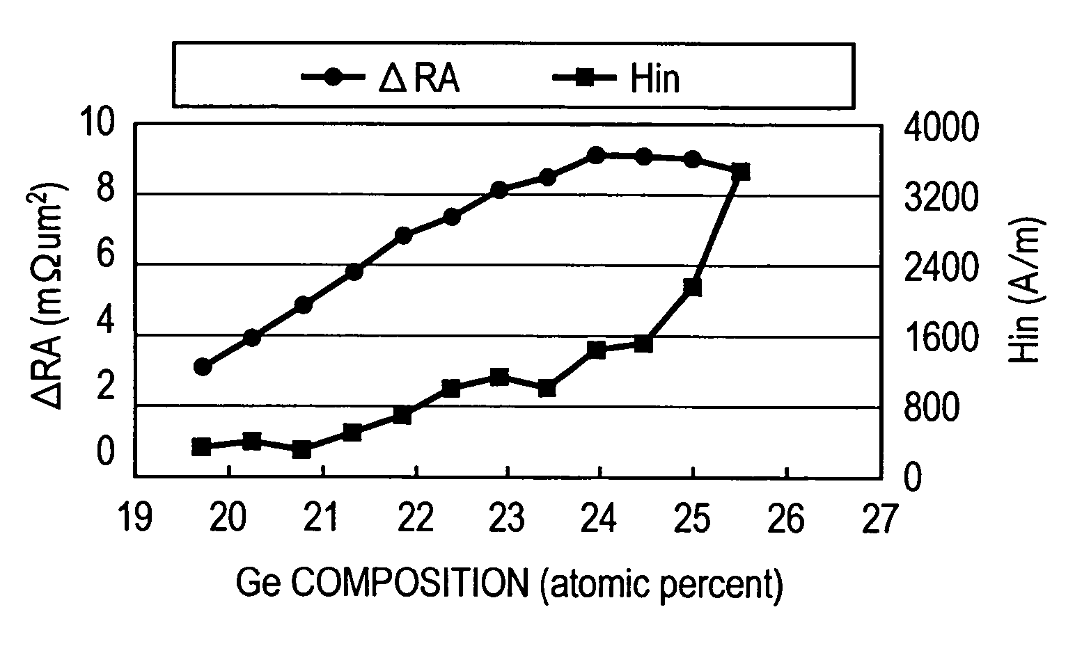
[0190] Film formation of a dual spin-valve type magnetic sensing element having a laminated structure described below was conducted, and the ferromagnetic coupling magnetic field Hin between a free magnetic layer and a pinned magnetic layer and the product ΔRA of the amount of change ΔR in magnetic resistance and the element area A of the magnetic sensing element were measured when the atomic percentage of Ge in a (Co0.67Mn0.33)aGeb alloy (where a and b represent atomic percentages, and a+b=100 atomic percent) serving as a material for the free magnetic layer was changed.

[0191] Substrate / substrate layer Ta (30 angstroms) / seed layer NiFeCr (50 angstroms) / antiferromagnetic layer IrMn (70 angstroms) / first pinned magnetic layer Co70Fe30 / non-magnetic intermediate layer Ru (9.1 angstroms) / second pinned magnetic layer (Co60Fe40 (10 angstroms) / Co2MnGe alloy layer (40 angstroms)) / non-magnetic material layer Cu (43 angstroms) / free magnetic layer ((Co0.67Mn0.33)aGeb (where a and b represent a...


PUM

PropertyMeasurementUnit
thicknessaaaaaaaaaa
thicknessaaaaaaaaaa
thicknessaaaaaaaaaa

Abstract

A magnetic sensing element which allows a high reproduction output and reduction in asymmetry of reproduction waveform to become mutually compatible, as well as a method for manufacturing the same, is provided. In the inside of a second pinned magnetic layer and a free magnetic layer, the atomic percentage of an element Z is decreased in a region close to a non-magnetic material layer. Consequently, the ferromagnetic coupling magnetic field due to magnetostatic coupling (topological coupling) between the pinned magnetic layer and the free magnetic layer can be reduced. At the same time, in a region at a distance from the non-magnetic material layer, the atomic percentage of an element Z is increased, a spin-dependent bulk scattering coefficient is increased, and a product of the amount of change in magnetic resistance and the element area of the magnetic sensing element can be maintained at a high level.

Description

BACKGROUND OF THE INVENTION [0001] 1. Field of the Invention [0002] The present invention relates to a magnetic sensing element including a pinned magnetic layer, in which the magnetization direction is pinned in one direction, and a free magnetic layer disposed on the above-described pinned magnetic layer with a non-magnetic material layer therebetween. In particular, it relates to a magnetic sensing element capable of stabilizing a reproduction output. [0003] 2. Description of the Related Art [0004]FIG. 9 is a partial sectional view of a known magnetic sensing element (spin-valve type thin film element) cut from a direction parallel to a surface facing a recording medium. [0005] Reference numeral 1 shown in FIG. 9 denotes a substrate layer made of Ta, and a seed layer 2 made of NiFeCr or the like is disposed on the substrate layer 1. [0006] A multilayer film T, in which an antiferromagnetic layer 3, a pinned magnetic layer 4, a non-magnetic material layer 5, a free magnetic layer ...

Claims


Application Information

Patent Timeline
Patent Type & Authority Applications(United States)
IPC IPC(8): C23C14/00G11B5/33G11B5/127
CPCB82Y25/00B82Y40/00C23C14/025C23C14/165C23C14/584G11B5/3903Y10T428/115H01F10/3268H01F41/302H01L43/10Y10T428/1121Y10T428/1193H01F10/1936H10N50/85
Inventor IDE, YOSUKESAITO, MASAMICHIISHIZONE, MASAHIKOHASEGAWA, NAOYA
Owner TDK CORPARATION
Why Eureka
Try Eureka