
Demodulator and phase compensation method thereof

Inactive Publication Date: 2006-08-24
NEC CORP
View PDF3 Cites 8 Cited by
  • Summary
  • Abstract
  • Description
  • Claims
  • Application Information

AI Technical Summary

Benefits of technology

[0018] The present invention has been made to solve, the above and other exemplary problems, and therefore an exemplary feature of the present invention is to eliminate effectively a phase fluctuation which cannot be fully eliminated by a carrier recovery loop (feedback loop), with subsequent feed-forward phase compensation loop which shares a phase detector of the carrier recovery loop.
[0021] Furthermore, in order to attain the above-mentioned and other exemplary features, the present invention provides an exemplary demodulator. The demodulator includes: a quadrature detector which converts a received signal to base-band signals of in-phase channel and quadrature-phase channel with multiplying by a local oscillation frequency; low-pass filters which eliminate high frequency components more unnecessary from the base-band signals; analog-to-digital converters (A / D) which convert the base-band signals after filtering into digital signals; a carrier recovery loop which detects a phase shift of the digital signals to a predefined phase position, and compensates for a phase of the digital signal by a first compensation value on the basis of the detected phase shift to generate an output signal; and a feed-forward phase compensation loop which generates an average value of the detected phase shift, and compensates for a phase of a signal output from the carrier recovery loop by a second compensation value on the basis of the averaged phase shift.
[0022] According to the above structure, the exemplary demodulator of the present invention can eliminate effectively a phase fluctuation which cannot be fully eliminated by a carrier recovery loop (feedback loop), with subsequent feed-forward phase compensation loop (feed-forward loop) which shares a phase detector of the carrier recovery loop.

Problems solved by technology

If the phase rotation remains, a transmitting data can not be recovered correctly (demodulation errors occur).
However, in the conventional carrier recovery loop, there is a problem that the phase rotation cannot fully be eliminated.
However, phase detector output contains generally a noise component (phase noise) incidental on phase detector itself regardless of phase fluctuation of the received signal.
Therefore, in the state where there is no line switching, while the feed-forward phase compensation loop has been in a state of operation, the phase noise remains and there is a problem of degrading the demodulation characteristic on the contrary.
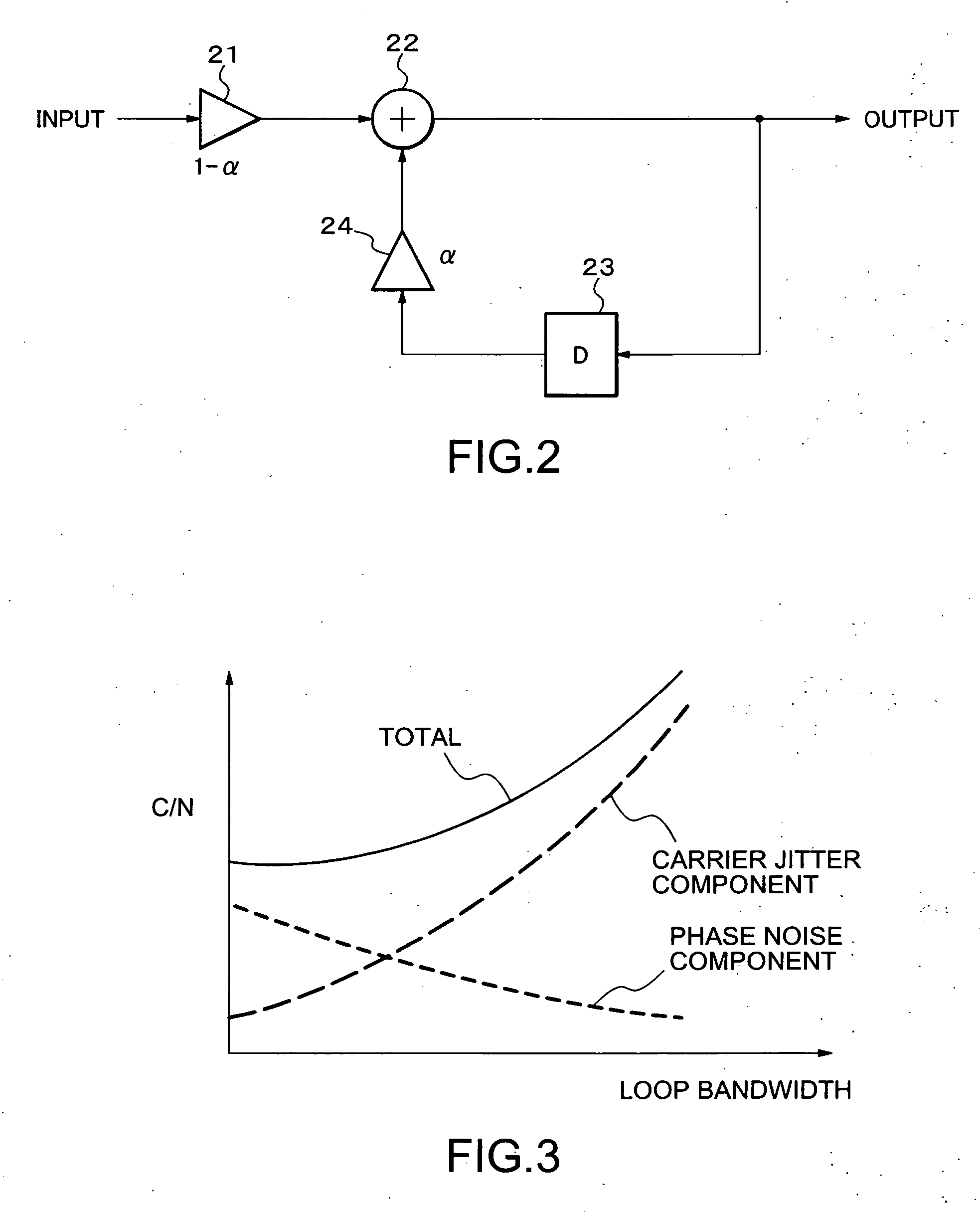
Meanwhile, as loop bandwidth is wide, C / N degradation by phase noise becomes small, but C / N degradation by the carrier jitter becomes large on the contrary.
Therefore, when the feed-forward phase compensation loop is effective in a state without line switching, the conventional demodulator mentioned above has the problem of degrading the demodulation characteristic on the contrary.

Method used


Image

  • Demodulator and phase compensation method thereof
  • Demodulator and phase compensation method thereof
  • Demodulator and phase compensation method thereof

Examples


Embodiment Construction

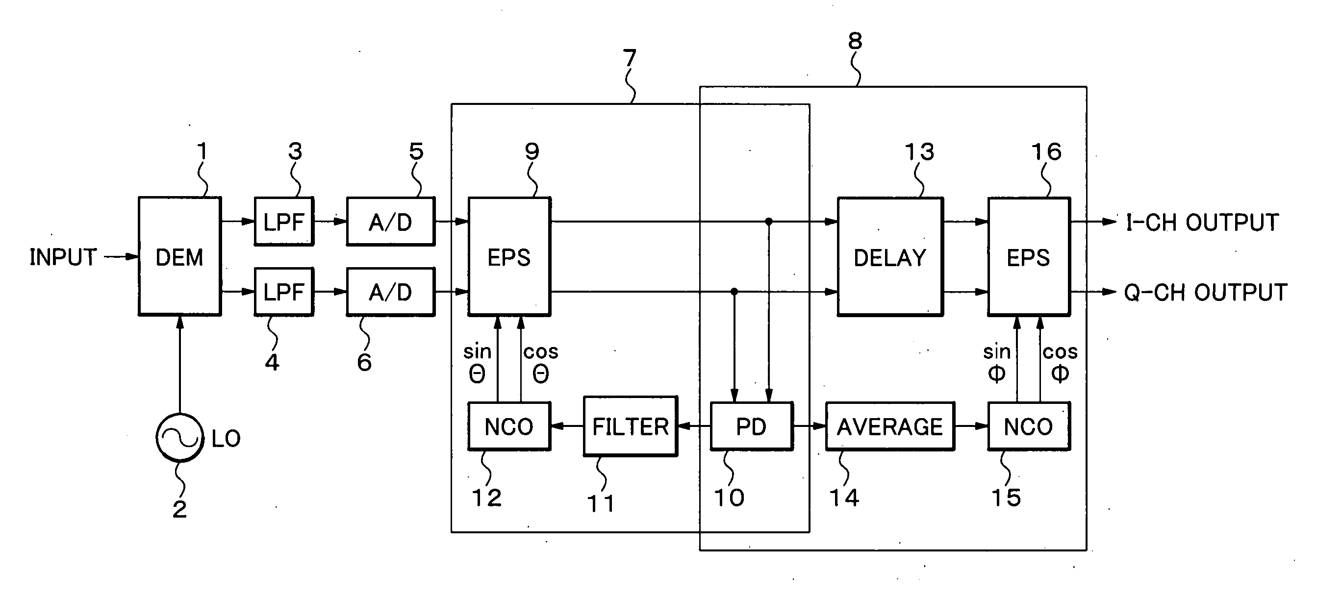
[0029] Hereinafter, a description will be given in more detail of an exemplary demodulator according to the present invention with reference to the accompanying drawings. FIG. 1 is a block diagram showing a structure of a demodulator according to an exemplary embodiment of the present invention.

[0030] Referring to FIG. 1, the demodulator according to the exemplary embodiment of the present invention includes a quadrature detector (DEM) 1, a local oscillator (LO) 2, low pass filters (LPF) 3 and 4, analog-to-digital converters (A / D) 5 and 6, a carrier recovery loop 7, a feed-forward phase compensation loop 8.

[0031] The carrier recovery loop 7 includes an endless phase shifter (EPS) 9, a phase detector (PD) 10, a loop filter 11, a numeric control oscillator (NCO) 12. Moreover, the feed-forward phase compensation loop 8 includes a delay circuit 25. (DELAY) 13, an average circuit (AVERAGE) 14, a numerical control oscillator (NCO) 15, and an endless phase shifter (EPS) 16 in addition to...


PUM


Abstract

The exemplary demodulator of the present invention can eliminate effectively a phase fluctuation which cannot be fully eliminated by a carrier recovery loop (feedback loop), with subsequent feed-forward phase compensation loop which shares a phase detector of the carrier recovery loop. A carrier recovery loop receives a digital signal after a semi-synchronous detection, detects a phase shift of the digital signal to a predefined phase position in rectangular coordinate, and compensates for the phase of the received digital signal by a first compensation value on the basis of the detected phase shift to generate an output signal. A feed-forward phase compensation loop generates an average value of the phase shift, and compensates for the phase of the output signal by a second compensation value on the basis of the averaged phase shift value.

Description

BACKGROUND OF THE INVENTION [0001] 1. Field of the Invention [0002] The present invention relates to a demodulator and phase compensation method, and more particularly, to a demodulator and phase compensation method capable of reducing effectively phase fluctuation incidental on semi-synchronous detection in a digital radio communication. [0003] 2. Description of the Related Art [0004] Heretofore, semi-synchronous detection is used as a demodulator of a digital radio communication. In the semi-synchronous detection, since a local oscillation (LO) frequency is not completely identical to a carrier frequency of a received signal, phase rotation (phase fluctuation) according to these frequency differences remains in a base-band signal after demodulation. [0005] If the phase rotation remains, a transmitting data can not be recovered correctly (demodulation errors occur). Correspondingly, as technology of eliminating this phase rotation, a carrier recovery loop is used in general. [0006]...

Claims


Application Information

Patent Timeline
IPC IPC(8): H04B1/16
CPCH04L27/0014H04L2027/003H04L2027/0046H04L2027/0057
Inventor ADACHI, TAKAHIRO
Owner NEC CORP
Learn More