Method and system for determining club head speed

a technology of club head speed and speed, applied in the field of method and system for determining club head speed, can solve the problems of burdensome unneeded information and limited existing techniques for measuring club head speed, and achieve the effects of convenient use, light weight and portability

Inactive Publication Date: 2006-08-24
TERRA SCIENTIA LLC
View PDF5 Cites 8 Cited by
  • Summary
  • Abstract
  • Description
  • Claims
  • Application Information

AI Technical Summary

Benefits of technology

[0009] In an embodiment of the present invention, the trajectory and direction of the golf ball can be determined employing a modified line scanning imager with one or more independent lines, such as right, center and left line scanning imagers. The signals to these imagers can be analyzed to determine the direction of the golf ball. By use of two line scan imagers one separate and one attached or integrated to the club head of a golf club, the golf ball trajectory may be determined. In an embodiment of the present invention, a more detailed analysis of the golf swing can be made using a two dimensional imager where both trajectory and direction may be determined. In an embodiment of the present invention, the imaging system is attached or integrated on the shaft just above the club head. The information obtained by the imaging system can be transmitted to a hand-held device for analysis and display of the results. In an embodiment of the present invention, the imaging system can be used separately from the golf club without significant alignment. The imaging system is intended to be portable and light weight such that it is readily usable during a game of golf or on a practice range.

Problems solved by technology

However, the existing techniques to measure club head speed are limited by the need to set up relatively complex optical or electronic devices, the need for alignments of devices, or the need to modify quality golf clubs changing their balance and affecting a player's performance.
In addition, the multiple two dimensional image arrays, for example 2,000×2,000 pixels or 4,000,000 pixels obtained in such measurements, contain excessive amounts of unneeded information that are a burden to analyze and discard in what needs to be light weight portable equipment.

Method used


Image

  • Method and system for determining club head speed
  • Method and system for determining club head speed
  • Method and system for determining club head speed

Examples


Embodiment Construction

[0013] The present invention is now described more fully hereinafter with reference to the accompanying drawings that show embodiments of the present invention. The present invention, however, may be embodied in many different forms and should not be construed as limited to embodiments set forth herein. Appropriately, these embodiments are provided so that this disclosure will be thorough and complete, and will fully convey the scope of the present invention.

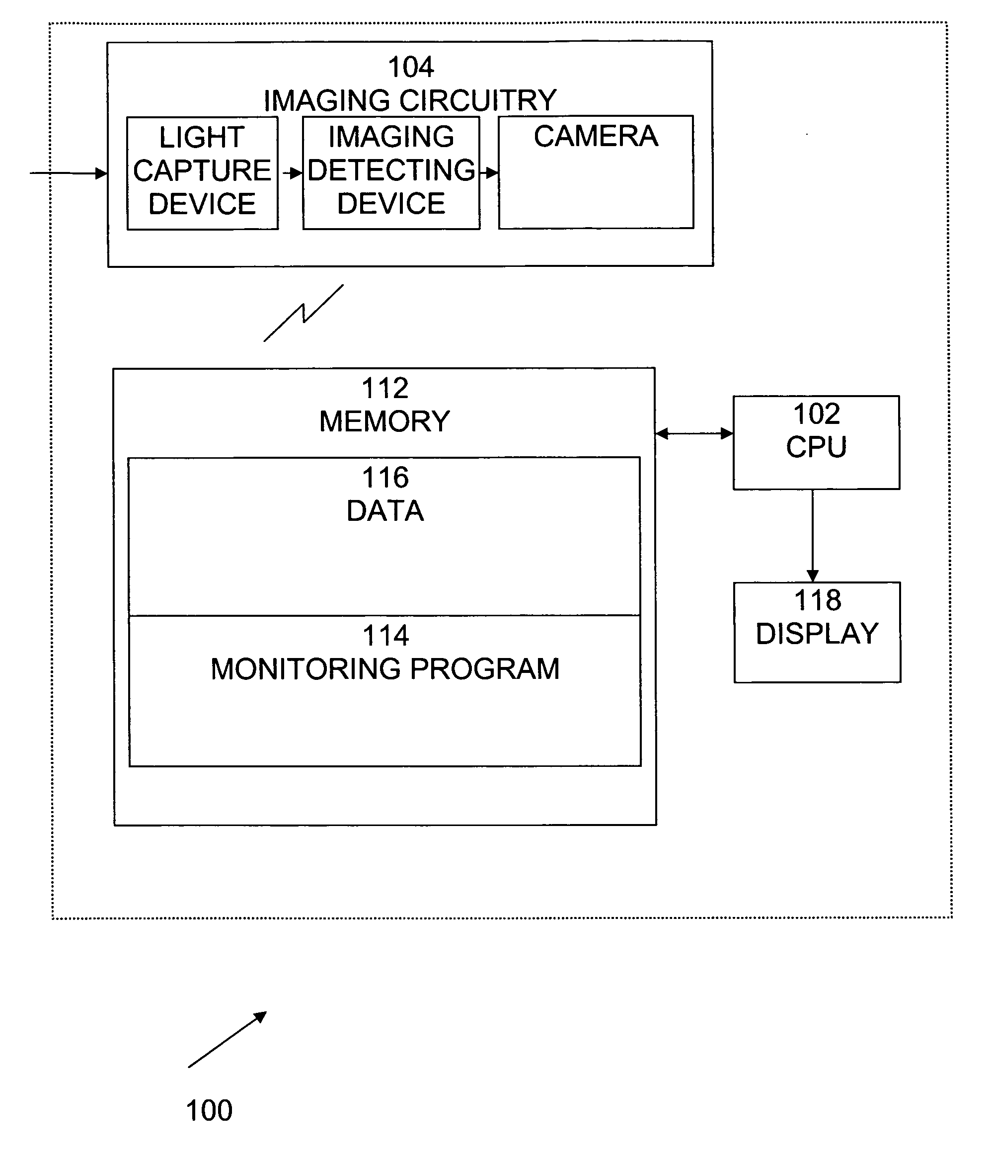
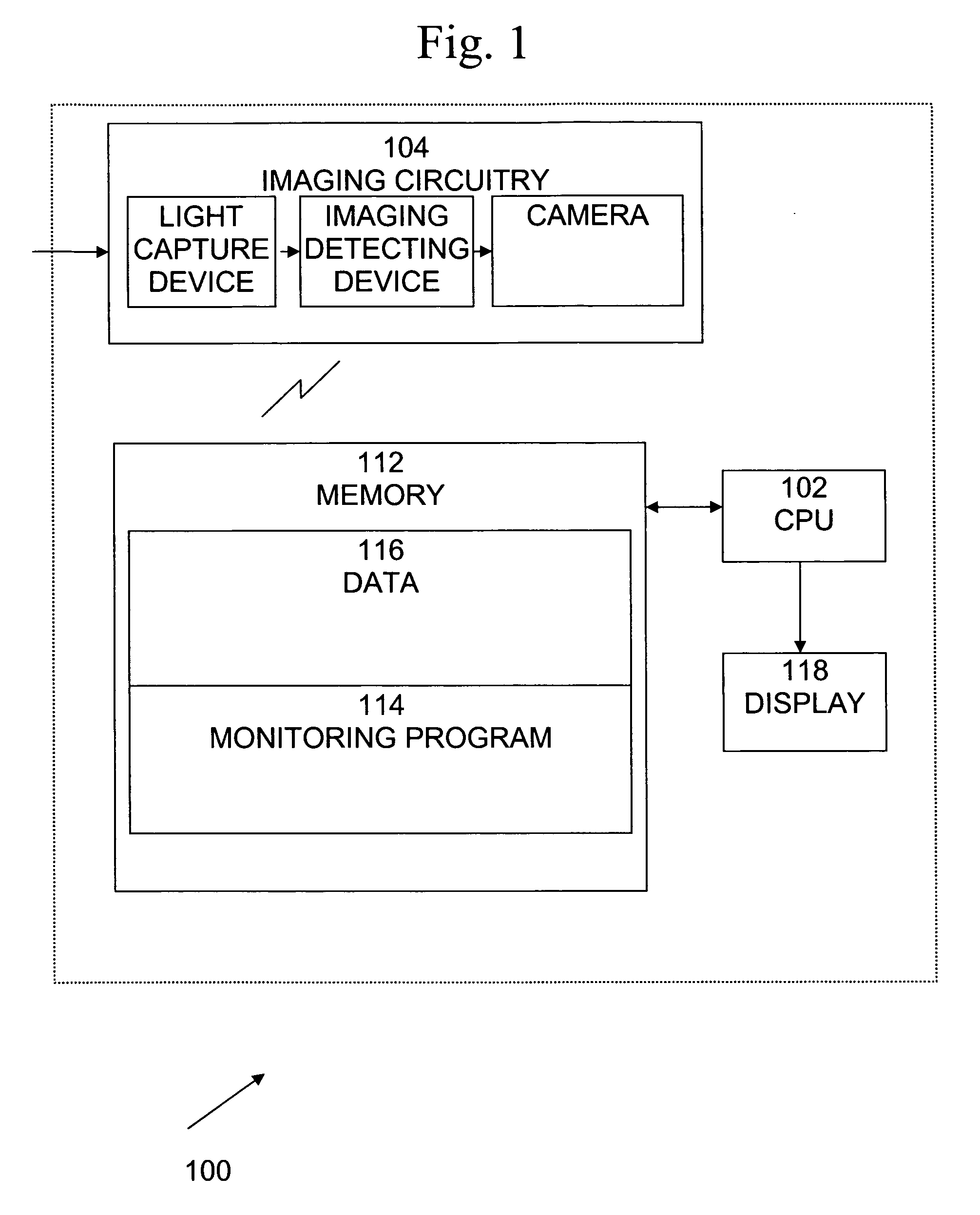
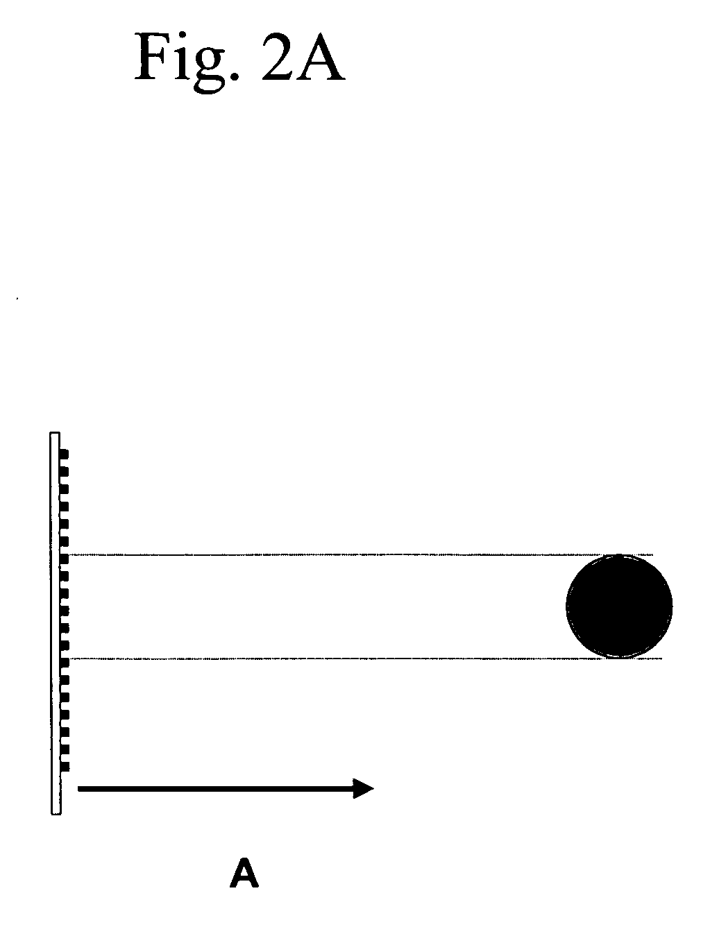
[0014] The time frame at which the club head reaches maximum velocity prior to striking a golf ball is between 0.03-0.003 seconds. In order to monitor club head speed, the present invention operates at speeds between a microsecond and a millisecond. In addition, the present invention uses a one dimensional (1D) line imaging system that operates at a scanning (clock) rate of between 10-40 MHz. A line image is analyzed in real time by an associate computer imaging system removing the need for a trigger to operate. Optics of the i...


PUM


Abstract

A one dimensional (1D) line imaging system that operates at a scanning (clock) rate of between 10-40 MHz is used to monitor the characteristics of a golf swing. A line image is analyzed in real time by an associate computer imaging system removing the need for a trigger to operate. Optics of the imaging system are designed to relate ball image size to distance so that the number of 1 D pixels imaging the ball, in particular sensing a white object, have a relation to distance to the ball. Ball image size is related to distance by monitoring the rate of increase (rate of change) of the pixels imaging the ball with time so that the speed of the club head can be determined. The speed of a golf ball that has been struck is determined by monitoring the rate of decrease (rate of change) of the pixels imaging the ball.

Description

CROSS REFERENCE TO RELATED APPLICATIONS [0001] The present invention claims priority to provisional Patent Application No. 60 / 654,000 filed Feb. 18, 2005, the entirety of which is incorporated herein by reference.BACKGROUND OF THE INVENTION [0002] 1. Field of the Invention [0003] The present invention relates to a method, a system and a computer program product for determining club head speed. More particularly, the present invention relates to a method, a device and a computer program product for determining the characteristics of a swing including club head speed and golf ball speed. [0004] 2. Description of the Prior Art [0005] The distance a golf ball will travel depends on the velocity of the golf ball after it is struck. The golf ball velocity in turn depends on the velocity of the club head of a golf club striking the golf ball or momentum transfer, where momentum is defined as mass times velocity. Thus, both the mass of the club and its velocity or speed is important to golf...

Claims


Application Information

Patent Timeline
Patent Type & Authority Applications(United States)
IPC IPC(8): A63B69/36G01M99/00
CPCA63B24/0003A63B24/0021A63B47/008A63B57/00A63B69/3614A63B69/3617A63B69/3658A63B69/3676A63B69/3685A63B69/3688A63B2024/0031A63B2024/0034A63B2220/05A63B2220/13A63B2220/805A63B2220/806A63B2220/807A63B2225/50A63B2243/0029G01B11/2408A63B2102/32A63B69/362A63B60/46
Inventor ZANZUCCHI, PETER JOHNBERNSTEIN, JONATHAN
Owner TERRA SCIENTIA LLC
Why Eureka
Try Eureka