Vapor collection method and apparatus

a technology of vapor collection and apparatus, applied in lighting and heating apparatus, drying machines with progressive movements, furnaces, etc., can solve the problems of undesirable condensation of vapor, inability to selectively draw primarily the desired gas phase components, and inability to separate vapors from the diluted vapor stream, so as to improve the efficiency of solvent recovery and eliminate contamination problems

Inactive Publication Date: 2006-08-31
3M INNOVATIVE PROPERTIES CO
View PDF46 Cites 11 Cited by
  • Summary
  • Abstract
  • Description
  • Claims
  • Application Information

AI Technical Summary

Benefits of technology

[0008] The present method and apparatus is designed to substantially reduce the amount of dilution gas transported through the chamber. The use of a chamber in close proximity to the surface of the material and small negative pressure gradients enables the substantial reduction of dilution gas, namely M1. The pressure gradient, Δp, is defined as the difference between the pressure at the chamber's lower periphery, pc, and the pressure outside the chamber, po, wherein Δp=pc−po. The value of M1 is generally greater than zero but not greater than 0.25 kg / second / meter. Preferably, M1 is greater than zero but not greater than 0.1 kg / second / meter, and most preferably, greater than zero but not greater than 0.01 kg / second / meter.
[0031] The method and apparatus of the present invention are preferably used in combination with conventional gap drying systems. Gap drying systems generally convey a material through a narrow gap between hot plate and a condensing plate for the evaporation and subsequent condensation of evaporative components in the material. The configuration of the present apparatus, in various locations of a gap drying system, enables further capture of gas phase components which generally can be present in the adjacent gas phase on the surface of the material either prior to entering, or exiting a gap drying unit.

Problems solved by technology

Conventional open vapor collection systems generally utilize air handling systems that are incapable of selectively drawing primarily the desired gas phase components without drawing significant flow from the ambient atmosphere.
Thus the subsequent separation of vapors from the diluted vapor stream can be difficult and inefficient.
Additionally, the thermodynamics associated with the conventional vapor collection systems often permit undesirable condensation of the vapor at or near the substrate or material.
The condensate can then fall onto the substrate or material and adversely affect either the appearance or functional aspects of the material.

Method used


Image

  • Vapor collection method and apparatus
  • Vapor collection method and apparatus
  • Vapor collection method and apparatus

Examples


example 1

[0088] With reference to FIG. 7, an oven 100 with a direct fired heater box 102 was utilized in the present Example. The oven 100 had a supply air plenum 104 with multiple high velocity nozzles 106. These high velocity convection nozzles 106 were placed within 2.5 cm from the substrate material 108. The material 108 was a web of plastic film having a semi-rigid vinyl dispersion coated on the surface. The high velocity nozzles 106, provided high heat transfer to the material 108. The discharge air velocity at the nozzle exit was 20-30 meters per second at the oven temperature. The heater box had a recirculation fan 110 and a modulating direct fired burner 112. The heater box mixed the recirculation air 114 with fresh make up air 116 and passed this through the heater box 102. The direct fired burner 112 was modulated to control discharge air temperature at 150° to 200° C. The desired operating pressure of the oven is maintained by controlling oven exhaust 118 and the make up air 116....

examples 2-5

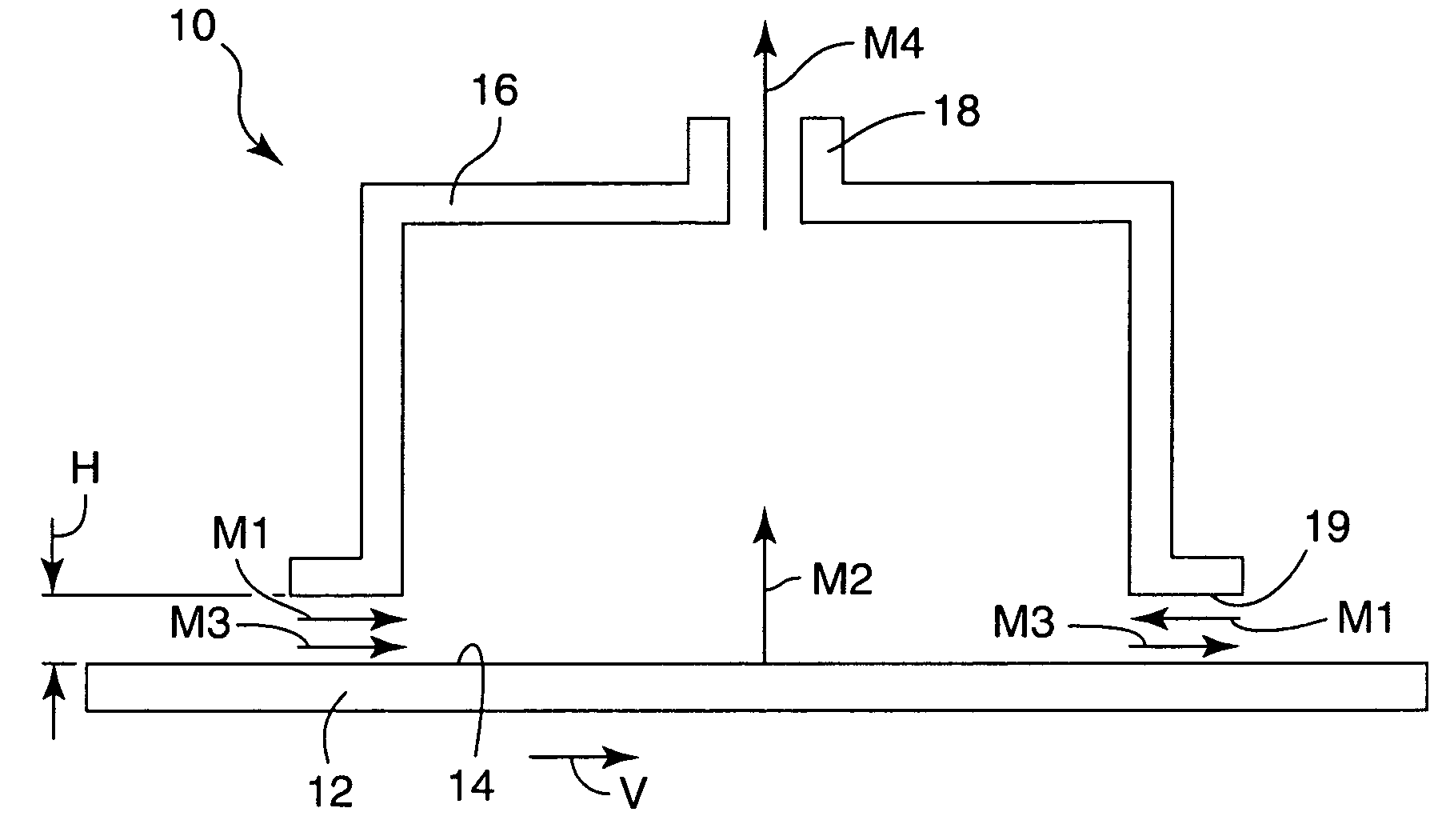
[0089] The comparison table below, Table 1, provides example calculations for different systems at typical equipment configurations and operating conditions. The definitions for M1, M2, M3, and M4 are the same as described above. M5 represents the time-average mass flow per unit width of any additional dilution stream provided to the chamber (for example the makeup air stream in convection ovens) in kg / second / meter. The width (“w”) of the material, in centimeters, is the measurement (of the gap) in the direction perpendicular to the motion of the material. The time-average gas phase velocity (“”) was defined above and has units of meters per second. The pressure difference (“ΔP”) is the pressure gradient between the lower periphery of the chamber and outside the chamber in Pascals. The material velocity (“V”) is measured in meters per second.

[0090] The average velocity of gas phase components through the gap, , can be measured using a velocity meter such as a hot wire anemometer, c...

example 4

[0093] In this example the vapor collection apparatus was integrated with a conventional gap drying system to capture and collect the gas phase components exiting the gap dryer. The web was conveyed by a conveying system through the apparatus of the present invention. The web was comprised of polyester film coated with inorganic material dispersed in ethanol and water. The web entered through an entrance gap having a width, w, of 30.5 cm and a height, H, of 0.32 cm. The material exited through an exit gap having the same dimensions as the entrance gap. The web was transported through the gap and underneath the chamber at a velocity of 0.015 meter / second. The exhaust flow M4 was measured to be 0.0066 kg / second / meter. The flow through the entrance and exit gaps out of the chamber, M1, resulting from the induced pressure gradient was approximately the same, 0.0066 kg / second / meter. M1 was calculated using Equation 1. The web and coating were for all practical purposes dry upon exiting t...


PUM


Abstract

An apparatus and method for treating a moving substrate of indefinite length. The apparatus has a control surface positioned in close proximity to a surface of the substrate to define a control gap between the substrate and the control surface. A first chamber is positioned near the control surface, with the first chamber having a gas introduction device. A second chamber is positioned near the control surface, the second chamber having a gas withdrawal device. The control surface and the chambers together define a region wherein the adjacent gas phases possess an amount of mass. Upon inducement of at least a portion of the mass within the region, the mass flow is controlled to significantly reduce dilution of the gas phase component in the adjacent gas phase. This is accomplished through the introduction of a controlled gas stream thereby reducing the flow of an uncontrolled ambient gas stream due to pressure gradients in the system.

Description

CROSS REFERENCE TO RELATED APPLICATIONS [0001] This application claims priority as a continuation of U.S. application Ser. No. 10 / 421,195, filed on Apr. 23, 2003 which in turn is a continuation-in-part of U.S. application Ser. No. 09 / 960,131, filed on Sep. 21, 2001 (now U.S. Pat. No. 6,553,689), which in turn claims priority to U.S. Provisional Application Ser. Nos. 60 / 235,214, filed on Sep. 24, 2000, 60 / 235,221, filed on Sep. 24, 2000, and 60 / 274,050, filed on Mar. 7, 2001, all of which are hereby incorporated by reference in their entirety.FIELD OF THE INVENTION [0002] The present invention relates to a vapor collection method, and more particularly to a method that enables the collection of gas phase components without substantial dilution. BACKGROUND OF THE INVENTION [0003] Conventional practices for the removal and recovery of components during drying of coated materials generally utilize drying units or ovens. Collection hoods or ports are utilized in both closed and open dryi...

Claims


Application Information

Patent Timeline
Patent Type & Authority Applications(United States)
IPC IPC(8): F26B3/00F26B13/00F26B25/00
CPCF26B13/005F26B13/10F26B25/006F26B13/00F26B25/00
Inventor MILLER, CRAIG A.JAIN, NIRMAL K.KOLB, WILLIAM BLAKE
Owner 3M INNOVATIVE PROPERTIES CO
Why Eureka
Try Eureka