Pressure abnormality detecting device for injection molding machine

a technology of abnormal pressure detection and injection molding machine, which is applied in the direction of measurement devices, fluid pressure measurement by mechanical elements, instruments, etc., can solve the problems of abnormal increase of resin pressure, mold damage, injection cylinder, nozzle, etc., and achieve the effect of precise prediction of injection pressur

Active Publication Date: 2006-08-31
FANUC LTD
View PDF9 Cites 16 Cited by
  • Summary
  • Abstract
  • Description
  • Claims
  • Application Information

AI Technical Summary

Benefits of technology

[0019] According to the present invention, if it is predicted that an injection pressure which is likely to exceed the predetermined limit pressure, the injection screw is adapted to stop, so that the injection pressure will not exceed the predetermined limit pressur

Problems solved by technology

An excessive increase in pressure will result in damage to a mold, injection cylinder, and nozzle, so that an automatic control has been performed by detecting an abnormal increase in pressure using some sort of means to stop an injection operation.
Even if the injection operation is stopped, a slight advance of the injection screw during deceleration (inertial flow) can not be avoided due to the inertia of a driving system for the injection screw, leading to an abnormal increase in a resin pressure, which may break a mold, injection cylinder, and nozzle.
However, when the injection pressure has been detected with this method, the injection pressure had already exceeded the set upper limit.
An excessive margin may stop the injecti

Method used


Image

  • Pressure abnormality detecting device for injection molding machine
  • Pressure abnormality detecting device for injection molding machine
  • Pressure abnormality detecting device for injection molding machine

Examples


Embodiment Construction

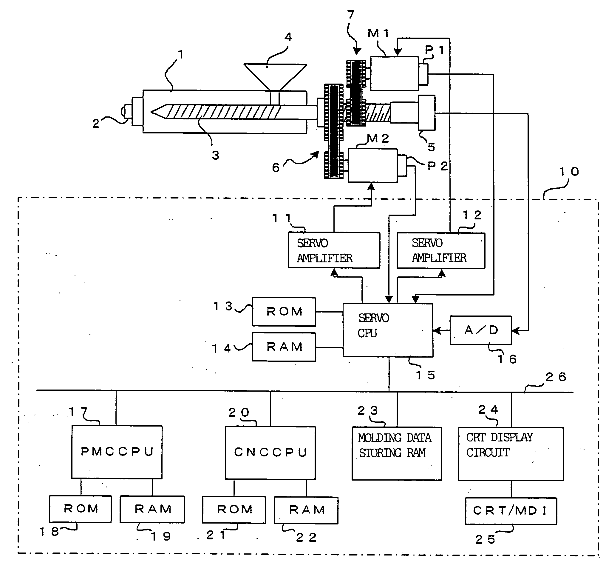
[0026]FIG. 1 is a block diagram of the principal elements showing one embodiment in which a pressure abnormality detecting device according to the present invention is applied to an electric injection molding machine.

[0027] A nozzle portion 2 is fitted to the end of an injection cylinder 1. An injection screw 3 is inserted into the injection cylinder 1. On the injection screw 3 is provided a pressure sensor 5 such as a load cell for detecting resin pressure by the pressure applied to the injection screw 3. The injection screw 3 is rotated with a screw rotating servomotor M2 through a transmission means 6 composed of a pulley, belt and the like. The injection screw 3 is driven with an injection servomotor M1 via a transmission means 7 including a mechanism for converting the rotational motion of the pulley, belt, and ball screw / nut mechanisms into a linear motion to be moved in the direction of the axis of the injection screw 3. In FIG. 1, reference character P1 denotes a position / s...


PUM

PropertyMeasurementUnit
Pressureaaaaaaaaaa
Speedaaaaaaaaaa

Abstract

An injection screw position Xa, injection speed Va, and injection pressure Pa are read. A deceleration distance D the injection screw moves from the point where the injection operation has been stopped at the current moment to be decelerated by maximum deceleration till the point where the injection speed is reduced to zero is determined from a corrected deceleration in which the amount of correction α is added to a predetermined deceleration A inherent in the machine and the read injection speed Va. The determined deceleration distance D is multiplied by the amount of change in injection pressure with respect to the amount of change in the injection screw position to determine a predicted increment in pressure (D·ΔP/ΔX). The predicted increment in pressure is added to the current injection pressure Pa to determine an injection pressure Pa* predicted when the screw is suddenly decelerated at the current moment. If the predicted injection pressure Pa* exceeds the predetermined limit pressure Pmax, the injection operation is stopped to decelerate the screw.

Description

BACKGROUND OF THE INVENTION [0001] 1. Field of the Invention [0002] The present invention relates to a pressure abnormality detecting device for detecting abnormality of an injection pressure in an injection molding machine. [0003] 2. Description of the Related Art [0004] In an injection molding machine, an injection process is first performed in which an injection screw is advanced to inject molten resin inside an injection cylinder into a clamped mold, thereafter followed by such processes as dwelling, cooling, metering, mold opening, unloading parts, mold closing, and mold clamping. In the injection process, molten resin can choke a mold or a nozzle portion fitted at the end of an injection cylinder by the influence of resin temperature and others, thereby increasing an injection pressure. An excessive increase in pressure will result in damage to a mold, injection cylinder, and nozzle, so that an automatic control has been performed by detecting an abnormal increase in pressure ...

Claims


Application Information

Patent Timeline
IPC IPC(8): G01L7/00
CPCB29C45/50B29C45/768B29C45/77B29C2945/76006B29C2945/76066B29C2945/76083B29C2945/7611B29C2945/76163B29C2945/76187B29C2945/76381B29C2945/76933B29C2945/76939
Inventor UCHIYAMA, TATSUHIROKOBAYASHI, MINORUKOMIYA, SHINGO
Owner FANUC LTD
Why Eureka
Try Eureka