Multiple port cross-over design for frac-pack erosion mitigation

a cross-over design and multi-port technology, applied in the direction of fluid removal, earthwork drilling and mining, borehole/well accessories, etc., can solve the problems of reducing the protection of the device by the blast liner, affecting the radial distribution of slurry, and affecting the slurry flow rate. , to achieve the effect of reducing the erosion of the surrounding blast liner, reducing the radial distribution of slurry, and reducing the slurry flow ra

Active Publication Date: 2006-08-31
BAKER HUGHES INC
View PDF14 Cites 23 Cited by
  • Summary
  • Abstract
  • Description
  • Claims
  • Application Information

AI Technical Summary

Benefits of technology

[0009] The invention provides an improved system for use in gravel packing operations wherein solid materials, in slurry form, are flowed out of the flowbore of a working tool, into the production assembly, and then into the annulus of a wellbore. In preferred embodiments, a gravel packing placement system includes an extension sleeve that is landed in a wellbore and a service tool that is run inside the extension sleeve. The service tool contains a gravel placement mandrel that defines an axial flowbore along its length and two or more lateral slurry flow ports for communication of slurry from the flowbore to the interior of the wear sleeve / blast liner. The slurry flow ports are oriented so as to distribute the slurry in different outwardly radial directions. This helps improve the radial distribution of slurry into the entire surrounding annulus. In addition, it reduces erosion of the surrounding blast liner by distributing the erosive forces among different areas of the blast liner. In a currently preferred embodiment, there are two slurry flow ports (an upper and a lower slurry flow port) that are oriented in opposite radial directions from one another (i.e., they are phased 180 degrees apart). The slurry flow ports are also axially displaced from one another along the gravel placement mandrel body.
[0010] Another aspect of the invention provides for relatively equivalent flow rates or flow amounts through each of the slurry flow ports. In one embodiment, a hydraulic choke, in the form of a restriction throat is located within the flowbore of the gravel placement mandrel between the upper and lower slurry flow ports. The restriction throat helps to offset the natural tendency of pumped down slurry to primarily exit the lower slurry flow port by limiting the flow rate to the lower port and creating a high pressure zone that will urge the slurry toward the upper flow port. In an alternative embodiment, the lower port of the gravel placement mandrel has a smaller diameter opening than the upper port, thereby balancing the flow rate toward the upper port to provide for substantially equivalent flow rates between the two flow ports. Because erosion is a function of the square of the fluid velocity when sub-sonic, and up to the fourth power when super-sonic, a reduction of the flow velocity at any given flow port will greatly reduce erosional effects.
[0011] In yet another aspect of the present invention, improvements are provided in the geometry of the slurry flow ports to enhance the flow of slurry through them. In a preferred embodiment, the slurry flow ports are generally rectangular in shape and each provides a outwardly and downwardly oriented upper and lower surfaces to help direct the flow of slurry downwardly. The upper slurry flow port also includes an upper enlargement, or recess, which, during operation, provides a low pressure zone that helps to induce flow through the upper flow port.

Problems solved by technology

Gravel packing operations create significant erosion wear upon the components of the cross-over assembly as the gravel or proppant is flowed into the wellbore.
One area that tends to receive the most severe damage is around the exit aperture where the solid material exits the crossover tool through a slurry flow port and enters the inside of the production assembly.
However, the addition of a blast liner provides only a limited amount of protection for the device.
A problem that has been recognized by the inventor is that gravel packing systems of this type are limited in their ability to handle ultra high rate proppant slurry flows.
As a result, the solid material is not evenly distributed when exiting the wear sleeve.
An additional problem with conventional gravel packing systems is the erosion of the wear sleeve or blast liner.
The velocity of the proppant slurry leaving the slurry flow port, coupled with the larger flow volumes, causes erosion and ultimate failure of the wear sleeve and production assembly adjacent the flow port.

Method used


Image

  • Multiple port cross-over design for frac-pack erosion mitigation
  • Multiple port cross-over design for frac-pack erosion mitigation
  • Multiple port cross-over design for frac-pack erosion mitigation

Examples


Embodiment Construction

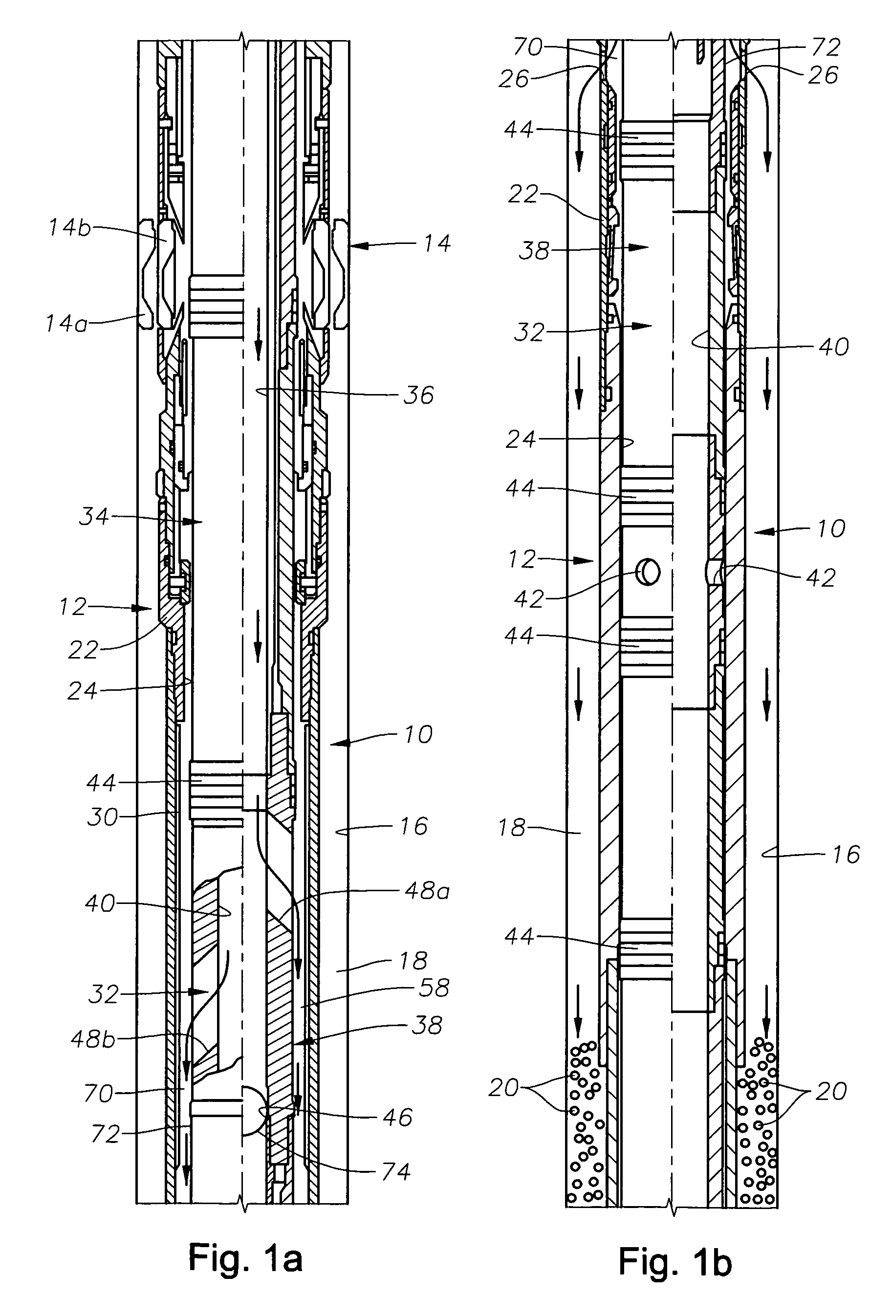
[0019]FIGS. 1a and 1b depict an exemplary solids placement system 10, which includes an extension sleeve assembly 12 that is secured to the lower end of a packer assembly 14. The packer assembly 14 is shown schematically in a set position at 14a and in an unset position at 14b. The exemplary solids placement system 10 is a system for the placement of gravel within a wellbore 16 during gravel packing. However, those of skill in the art will appreciate that a similar arrangement may be used for disposal of proppants and other solids within a wellbore. It is noted that the details of gravel packing and proppant placement operations generally are well known to those of skill in the art and, therefore, will not be described in detail herein. However, the general outline of an exemplary gravel packing tool and system 10 is described in order to illustrate the present invention.

[0020] The packer assembly 14 is a through-tubing packer assembly in that, once set, it can permit a service too...


PUM


Abstract

A system for use in gravel packing operations wherein a gravel placement mandrel defines an axial flowbore and two or more lateral slurry flow ports for communication of slurry from the flowbore to the interior of the wear sleeve / blast liner. The slurry flow ports are oriented so as to distribute the slurry in different outwardly radial directions. The slurry flow ports are also axially displaced from one another along the gravel placement mandrel body. Relatively equivalent flow rates or flow amounts are provided through each of the slurry flow ports. Improvements are also provided in the geometry of the slurry flow ports to enhance the flow of slurry through them.

Description

BACKGROUND OF THE INVENTION [0001] 1. Field of the Invention [0002] The invention relates generally to devices and methods for improved gravel packing operations within a wellbore. In more particular aspects, the invention relates to the design of devices that are used to place gravel or other solids in such operations. [0003] 2. Description of the Related Art [0004] During gravel packing, a slurry containing gravel or a proppant is pumped down a tubing string into a wellbore and placed where desired using a cross-over tool with suitable exit ports for placement of the gravel in desired locations within the wellbore. A typical conventional gravel packing cross-over tool is described, for example, in U.S. Pat. No. 6,702,020, issued to Zachman et al. This patent is owned by the assignee of the present invention and is hereby incorporated by reference. [0005] Gravel packing operations create significant erosion wear upon the components of the cross-over assembly as the gravel or proppa...

Claims


Application Information

Patent Timeline
Patent Type & Authority Applications(United States)
IPC IPC(8): E21B43/04
CPCE21B43/045E21B43/04
Inventor CORONADO, MARTIN P.
Owner BAKER HUGHES INC
Why Eureka
Try Eureka