Novel hollow fiber film separating device and its preparation method

A technology for separators and fiber membranes, applied in semipermeable membrane separation, chemical instruments and methods, membrane technology, etc., can solve the problems of reduced membrane separation performance, affecting membrane separation performance, and restricting hollow fiber gas separation membranes

Active Publication Date: 2012-07-18
TIANBANG NAT ENG RES CENT OF MEMBRANE TECH
View PDF0 Cites 0 Cited by
  • Summary
  • Abstract
  • Description
  • Claims
  • Application Information

AI Technical Summary

Problems solved by technology

At the same time, at the exhaust end of the separator, the high-pressure exhaust gas is mainly discharged through the annular gap between the end of the fiber bundle and the outer casing, and the gas flow is more concentrated on the surface of the hollow fiber membrane around the fiber bundle, which intensifies the internal pressure of the fiber bundle. Deterioration of the flow state of the hollow fiber membrane surface
In this way, for a gas membrane separator with a large outer diameter, on the one hand, the effective membrane area utilization rate of the hollow fiber gas separation membrane is reduced; the separation performance of the membrane
Due to some defects of the current hollow fiber gas membrane separator, the separation performance of the membrane separator is reduced, the concentration and flux of the permeated gas are affected, and the application of the hollow fiber gas separation membrane technology is restricted.

Method used


Image

  • Novel hollow fiber film separating device and its preparation method
  • Novel hollow fiber film separating device and its preparation method
  • Novel hollow fiber film separating device and its preparation method

Examples


Embodiment 1

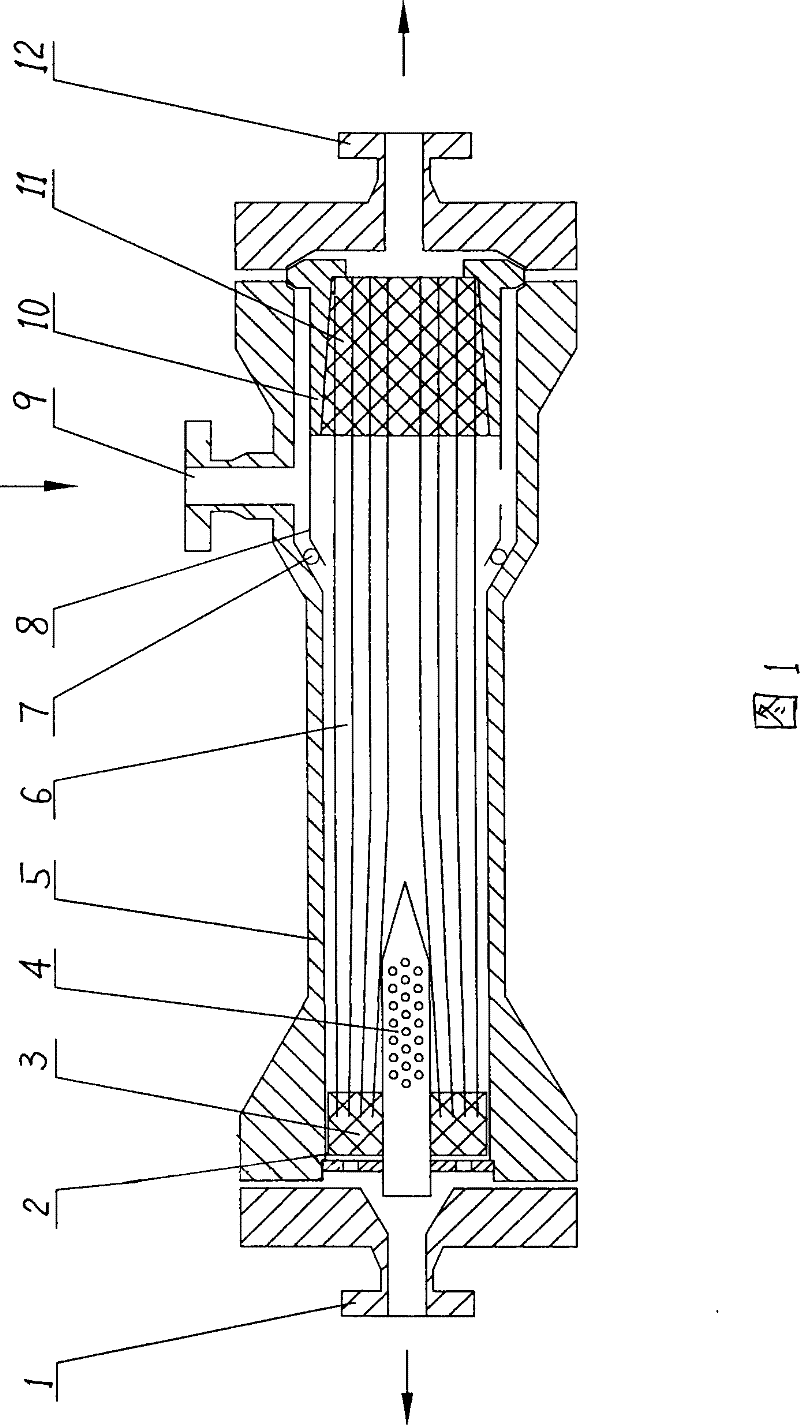
[0030] Such as figure 1 In the novel hollow fiber membrane separator shown, tens of thousands or hundreds of thousands of hollow fiber gas separation membranes are made into fiber bundles 6 and then installed in a pressure-resistant steel casing 5, and one end of the fiber bundles is bonded with a resin adhesive It is casted into a resin head 11 and fixed at one end of the separator through a fixing jacket 10. The other end of the fixing jacket 10 and the outer shell are sealed with an O-ring 7, and some raw materials are distributed on the outer surface of the fixing jacket. Gas guide holes 8, so that raw gas can enter the shell side of the membrane separator, and the inner cavity of the hollow fiber gas separation membrane communicates with the outside to form a permeable gas channel 12. The tail end of the fiber bundle is sealed with resin to form a plug 3, which is fixed at the other end of the separator. At the end of the plug 3, the gap between the hollow fiber gas separ...

Embodiment 2

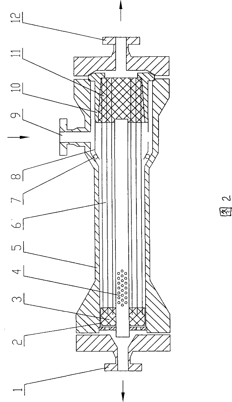
[0033] Such as figure 2 As shown, the basic structure is the same as that of Example 1, except that the tail gas collection pipe 4 at the tail end of the fiber bundle 6 is extended to the inside of the fiber bundle resin head 11, and the airflow mode in the separator is the same as that of Example 1. The exhaust gas collection pipe in the device also supports the fiber bundle.

Embodiment 3

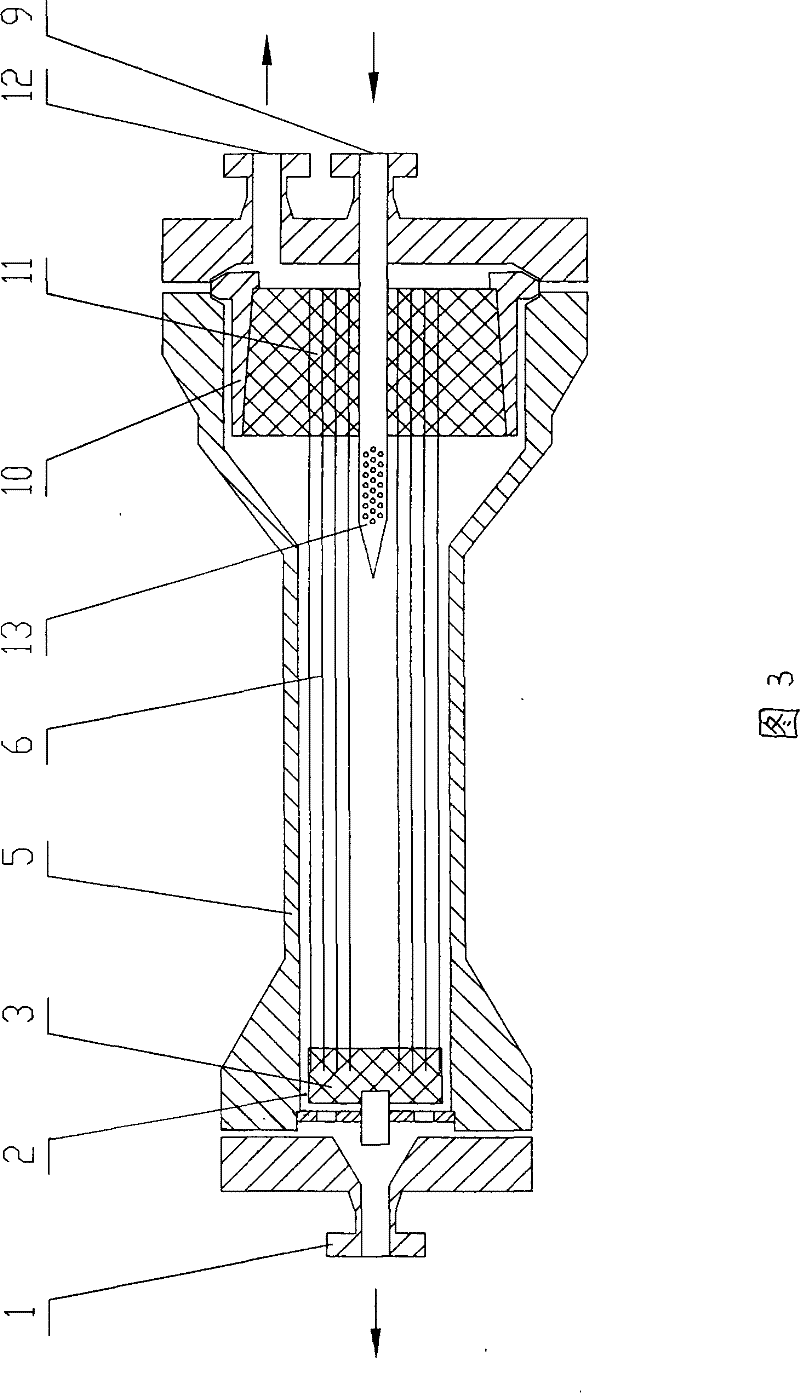
[0035] Such as image 3 As shown, the hollow fiber gas separation membrane is made into a fiber bundle 6 and then installed in a pressure-resistant steel casing 5. The exhaust gas discharge channel is the annulus 2 between the plug at the end of the fiber bundle and the casing. One end of the fiber bundle is used The resin adhesive is cast into a resin head 11, which is fixed at one end of the separator through a fixing jacket 10, and a center pipe is installed in the center of the resin head as a raw material gas distribution pipe 13 to form a raw material gas distribution pipe. The resin head 11, the position of the feed gas inlet 9 is changed directly above the resin head, connected with the feed gas distribution pipe 13, and opening holes on the surface of the feed gas distribution pipe to form the passage for the feed gas to enter the membrane separator. The opening area is usually between 0-500cm below the resin head 11, preferably between 20-200cm. The feed gas is fed ...


PUM


Abstract

The present invention relates to separator, and is especially one kind of hollow fiber membrane separator, which has one pressure-proof steel housing, gas separating hollow fiber bundles inside the housing and with two ends fixed through resin to the two ends of separator casing, one material gas inlet channel, and one tail gas exhausting channel with tail gas colleting pipe and / or ring gap. The hollow fiber membrane separator possesses two tail gas exhausting modes, improved gas flow mode, homogeneous radial distribution of material gas inside the fiber bundles and raised separating performance.

Description

Technical field: [0001] The invention relates to a membrane separator, especially a hollow fiber membrane separator, and also relates to a preparation method thereof. Background technique: [0002] Membrane separation technology is a new type of separation technology successfully developed in the 20th century. Compared with traditional separation technology, membrane technology has the characteristics of low investment, quick results, low energy consumption, and simple operation. Its development and utilization have become a hot spot in the high-tech field of various countries. With the development of membrane technology, gas membrane separation technology has been successfully applied to the recovery of hydrogen in the exhaust gas of synthetic ammonia; the recovery of hydrogen in the exhaust gas of methanol synthesis or the adjustment of CO / H2; the membrane hydrogen recovery of refinery gas, etc. separate fields. [0003] The core of membrane separation technology is the ...

Claims


Application Information

Patent Timeline
Patent Type & Authority Patents(China)
IPC IPC(8): B01D53/22B01D63/02
Inventor 任吉中李晖邢军刘玉花尹中升邓麦村
Owner TIANBANG NAT ENG RES CENT OF MEMBRANE TECH
Why Eureka
Try Eureka