
Automotive alternator having rectifier mounted on heatsink plate with cooling fins

a technology of heatsink plate and rectifier, which is applied in the direction of magnetic circuit rotating parts, magnetic circuit shape/form/construction, windings, etc., can solve the problems of high temperature in the engine compartment, unavoidable temperature rise in the alternator, and high water splashing by tires or foreign particles into the engine compartment, so as to improve the cooling efficiency

Inactive Publication Date: 2006-08-31
DENSO CORP
View PDF10 Cites 18 Cited by
  • Summary
  • Abstract
  • Description
  • Claims
  • Application Information

AI Technical Summary

Benefits of technology

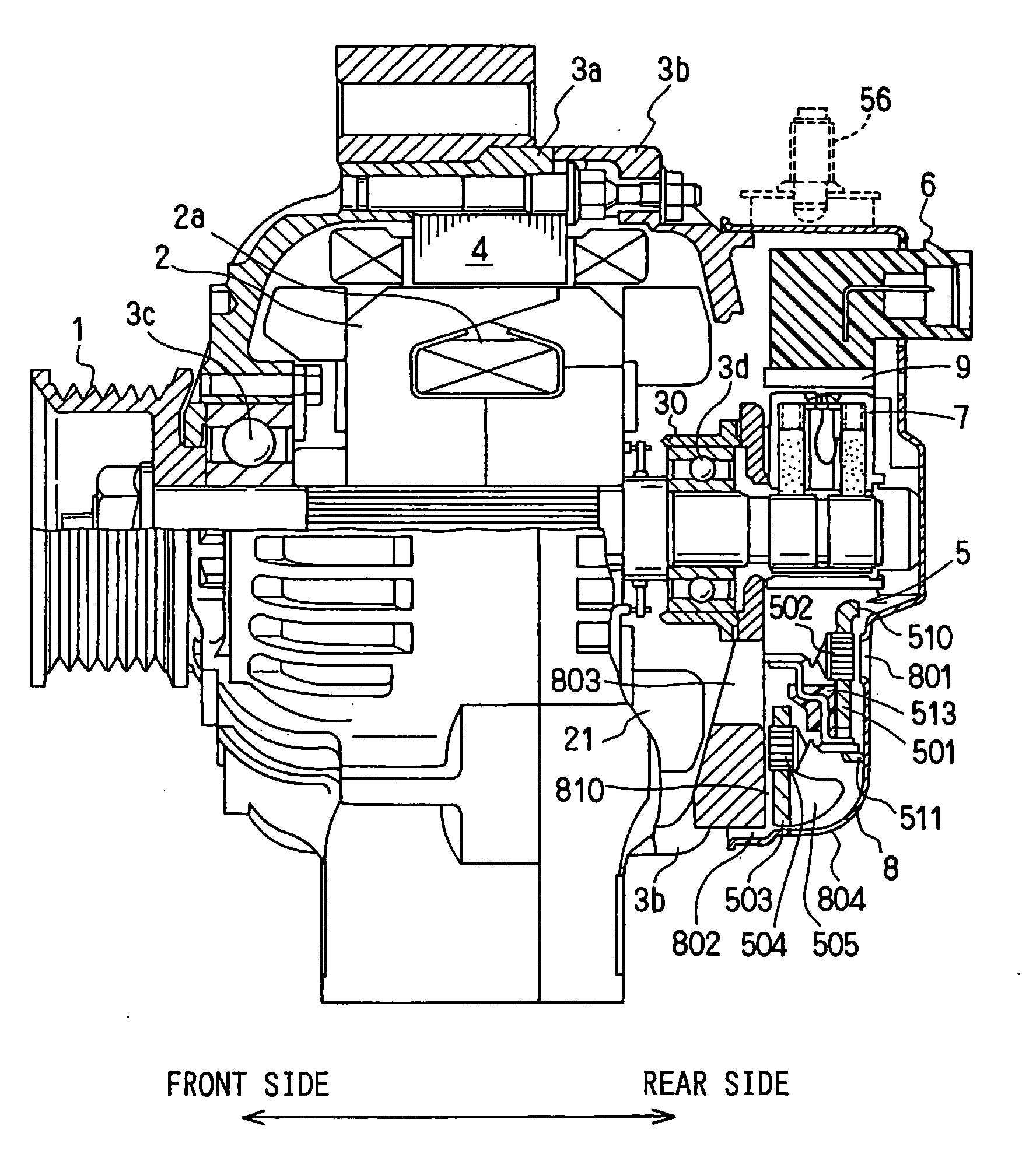
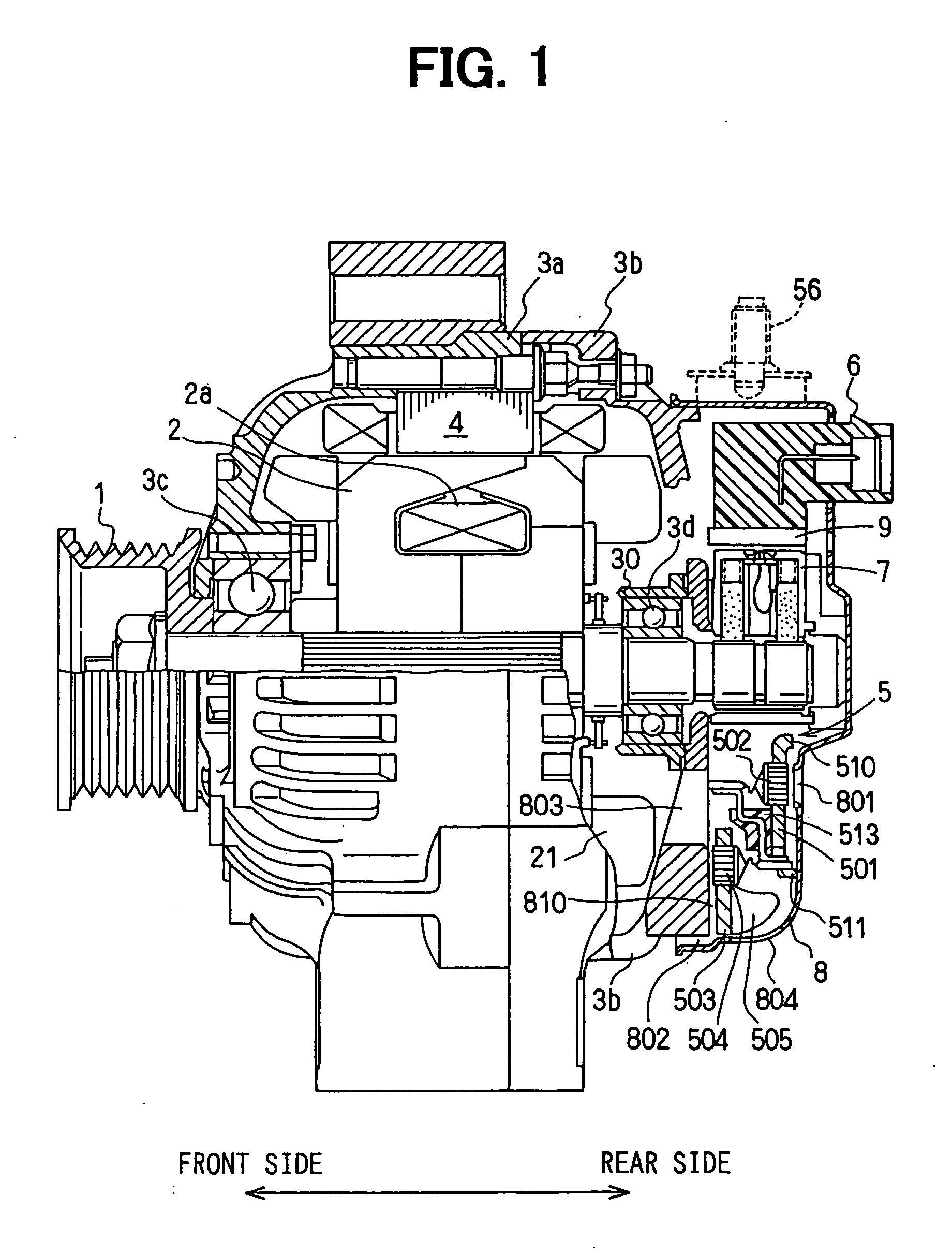
The present invention aims to improve the cooling efficiency and provide a better measure against water in an alternator used in automotive vehicles. The invention includes a two-story structure with cooling fins on the minus heatsink plate, which is placed to face the rear surface of the rear frame and the radial openings of the rear cover. The cooling air flows through the air passage between the minus heatsink plate and the rear frame, effectively cooling the minus heatsink plate from both surfaces. The plus heatsink plate is cooled through the axial openings and the radial openings. The invention also provides a means to easily drain water that may enter the alternator through the radial openings. Overall, the invention improves the cooling efficiency and provides better protection against water in the alternator.

Problems solved by technology

There is a tendency that temperature in the congested engine compartment becomes high.
Under these circumstances, it is unavoidable that a temperature rise in the alternator becomes higher, especially in a rectifier that converts alternating current to direct current.
Therefore, it is required to efficiently cool the rectifier in a limited space.
Because of the slant-nose design, a possibility that water splashed by tires or foreign particles enter into the engine compartment becomes high.
Though the radial air passage proposed by JP-A-11-164538 improves the cooling efficiency to a certain extent, the radial passage alone is not sufficient to cope with a temperature rise that is becoming higher and higher in recent high power alternators.
However, such a countermeasure is contradictory to a requirement for reducing the alternator size.

Method used


Image

  • Automotive alternator having rectifier mounted on heatsink plate with cooling fins
  • Automotive alternator having rectifier mounted on heatsink plate with cooling fins
  • Automotive alternator having rectifier mounted on heatsink plate with cooling fins

Examples


first embodiment

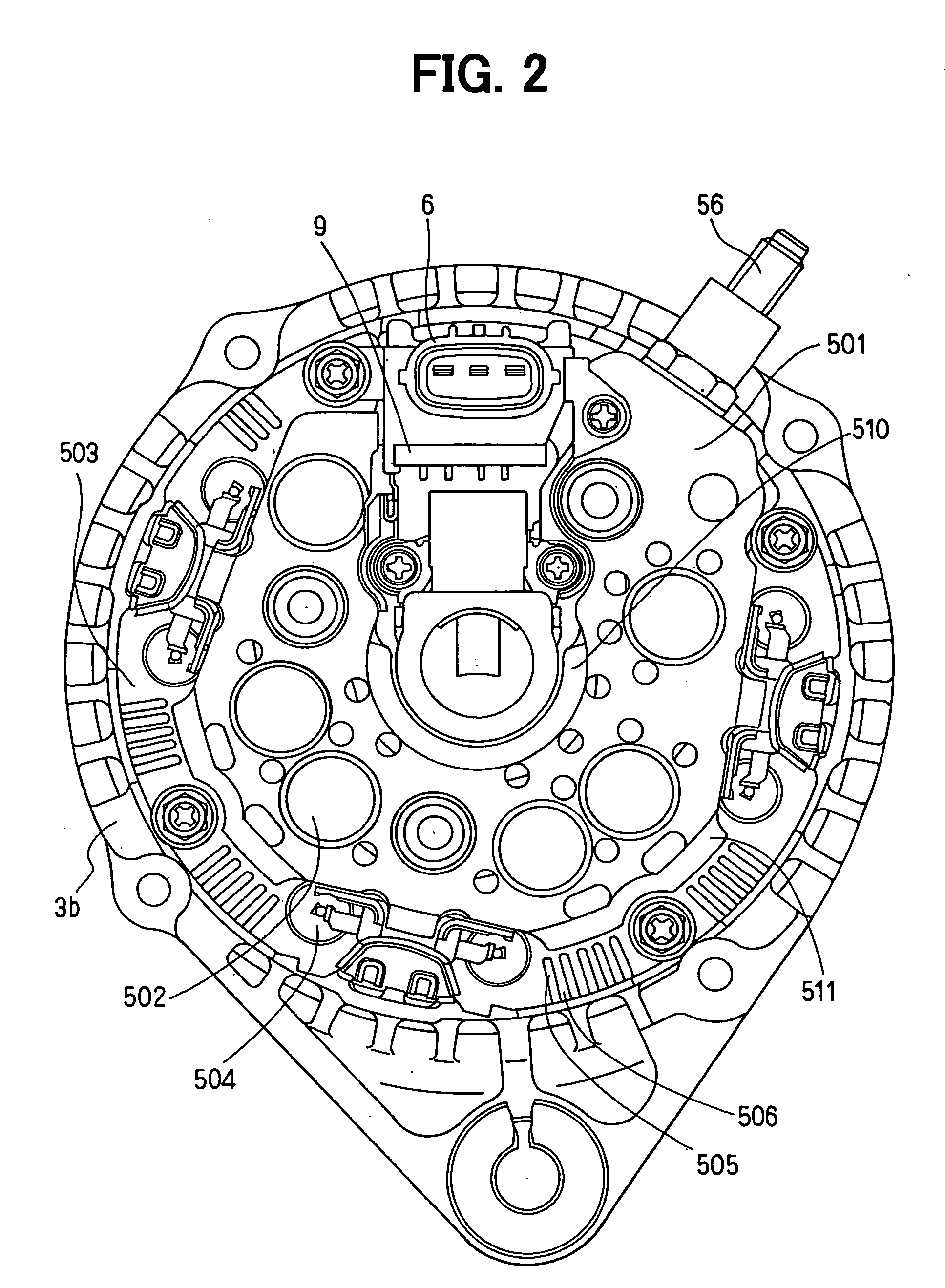
[0031] the present invention will be described with reference to FIGS. 1-6. An alternator is composed of: a housing including a front frame 3a and a rear frame 3b (a front side and a rear side of the alternator are indicated in FIG. 1); a cylindrical stator 4 having an armature coil, the stator being contained in the housing; a rotor 2 having a field coil 2a, the rotor 2 being rotatably supported by bearings 3c, 3d inside the cylindrical stator 4; a pulley 1 connected to the rotor 2 for transmitting a rotational torque from an engine; a rectifier 5 for converting alternating current generated in the armature coil into direct current, the rectifier 5 being mounted on the rear frame 3b; a brush holder 7 holding brushes for supplying current to the field coil 2a; a regulator 9 for controlling an output voltage to a predetermined voltage; a connector case 6 for electrically connecting alternator to an outside circuit; a rear cover 8 made of resin for covering the rectifier 5, the regula...

second embodiment

[0040] the present invention will be described with reference to FIG. 7. The air passage 810 leading the cooling air from the radial air gap 802 to the air inlet 803 may be constituted as shown in FIG. 7. Plural ditches forming the air passage 810 and plural projected surfaces 811 contacting the minus heatsink plate 503 are alternately formed on the rear frame 3b. The ditches and the projected surfaces are formed along radial lines converging to the center of the alternator. An air passage 810a facing a back surface of the minus diode 504 mounted on the minus heatsink plate 503 may be made shallower than other air passages 810, as shown in FIG. 7. In addition to making a direct contact between the projected surfaces 811 and the minus heatsink plate 503, a heat-conductive material such as heat-conductive grease may be placed therebetween. The plural projected portions forming the projected surfaces 811 also function as additional cooling fins. By constituting the air passage 810 in t...

third embodiment

[0041] the present invention will be described with reference to FIG. 8. In this embodiment, the rear cover 8 is eliminated, and the rear bearing 3d is disposed on the rear most end of the rear frame 3b. The rectifier 5 is disposed in a space between the rear frame 3b and a separating wall 10. Axial openings 801 a are formed on the axial end wall of the rear frame 3b, and radial openings 802a, 802b are formed on the radial wall of the rear frame 3b.

[0042] The rectifier 5 includes an outer heatsink plate 503a on which the plus diodes 502 are mounted and an inner heatsink plate 501a on which the minus diodes 504 are mounted. When the cooling fan 21 is rotated, cooling air introduced from the axial openings 801a is sucked into an air inlet port 101 formed on the separating wall 10 after cooling the inner heatsink plate 501a. Cooling air introduced from the radial openings 802b passes through the cooling fins 505 formed on the outer heatsink plate 503a and flows into the inner space th...


PUM


Abstract

A rotor and a stator are contained in a housing composed of front and rear frames, and a rectifier is mounted on the rear frame and covered with a rear cover having axial and radial openings. A minus heatsink plate having cooling fins extending in the axial direction is disposed to face the radial openings, forming radial air passages, and another air passage is formed between the minus heatsink plate and the rear frame. Cooling air introduced from the radial openings flows through the cooling fins and through the passage between the minus heatsink plate and the rear frame. Thus, efficiency for cooling the rectifier is enhanced.

Description

[0001] This is a Divisional of U.S. patent application Ser. No. 10 / 620,443 filed Jul. 17, 2003, which is hereby incorporated by reference in its entirety. This application claims priority to Japanese Patent Application No. 2002-253770 filed Aug. 30, 2002, and Japanese Patent Application No. 2003-96381 filed Mar. 31, 2003, which are hereby incorporated by reference in their entirety.BACKGROUND OF THE INVENTION [0002] 1. Field of the Invention [0003] The present invention relates to an alternator (an alternating current generator) for use in an automotive vehicle. [0004] 2. Description of Related Art [0005] An engine compartment size is becoming smaller in a recent vehicle to employ a so-called slant-nose design and to secure a sufficient space for a passenger compartment. There is a tendency that temperature in the congested engine compartment becomes high. In addition, a higher output of an alternator is required to fulfill power consumption in various electric and electronic device...

Claims


Application Information

Patent Timeline
Patent Type & Authority Applications(United States)
IPC IPC(8): H02K3/24H02K11/04H02K5/20H02K9/02H02K19/36
CPCH02K11/046H02K5/15H02K5/18H02K9/06H02K2213/03H02K5/207H02K11/05
Inventor IHATA, KOUICHINAKAMURA, SHIGENOBUITO, MOTOKIKOUMURA, MASATOSHI
Owner DENSO CORP
Learn More