
Image reading apparatus and imaging apparatus

Active Publication Date: 2006-08-31
RICOH KK
View PDF17 Cites 61 Cited by
  • Summary
  • Abstract
  • Description
  • Claims
  • Application Information

AI Technical Summary

Benefits of technology

[0011] According to a preferred embodiment of the present invention, a technique is provided for enabling immediate document size detection after switching back to standby mode from power-saving mode. According to another embodiment of the present invention, a technique is provided for maintaining high user operability.
[0020] According to an aspect of the present embodiment, since the optical unit is positioned at the document size detecting position before switching to sleep mode, the optical unit for projecting image light of the document on the image sensor does not have to be driven to the document size detecting position upon switching back to standby mode from sleep mode so that the document size may be immediately detected and high user operability may be maintained even when using a power circuit with a power saving mode.
[0026] According to an aspect of the present embodiment, by detecting the downward movement of the holding member, the document size may be swiftly detected in the short period of time in which the holding member is lowered and closed so that high user operability may be maintained even when using a power circuit with a power saving mode.
[0030] According to an aspect of the present embodiment, since the power circuit is switched back to standby mode when the holding member is raised and opened, a document may be placed and the holding member may be closed immediately therafter in a short period of time so that high user operability may be maintained even when a power circuit with a power saving mode is used.
[0034] According to an aspect of the present embodiment, document size detection may be performed ahead of time in consideration of the time required for initializing the sub scanning position information of the optical unit so that high user operability may be maintained even when using a power circuit with a power saving mode. Also, since the sub scanning position information is initialized after document size detection, the optical unit may be accurately positioned with respect to the sub scanning direction.
[0038] According to an aspect of the present embodiment, when power is supplied to the power circuit as a result of an external power source being connected to the power circuit, the actual sub scanning position of the optical unit may be deviated from the sub scanning position information due to mechanical oscillation during external power shutdown, manual maneuvering of the optical unit during maintenance, or test driving, for example. Thus, by initializing the sub scanning position information, the sub scanning position information may be arranged to accurately represent the position of the optical unit.

Problems solved by technology

However, there are drawbacks to using such a document size detection technique as is described below.

Method used


Image

  • Image reading apparatus and imaging apparatus
  • Image reading apparatus and imaging apparatus
  • Image reading apparatus and imaging apparatus

Examples


first embodiment

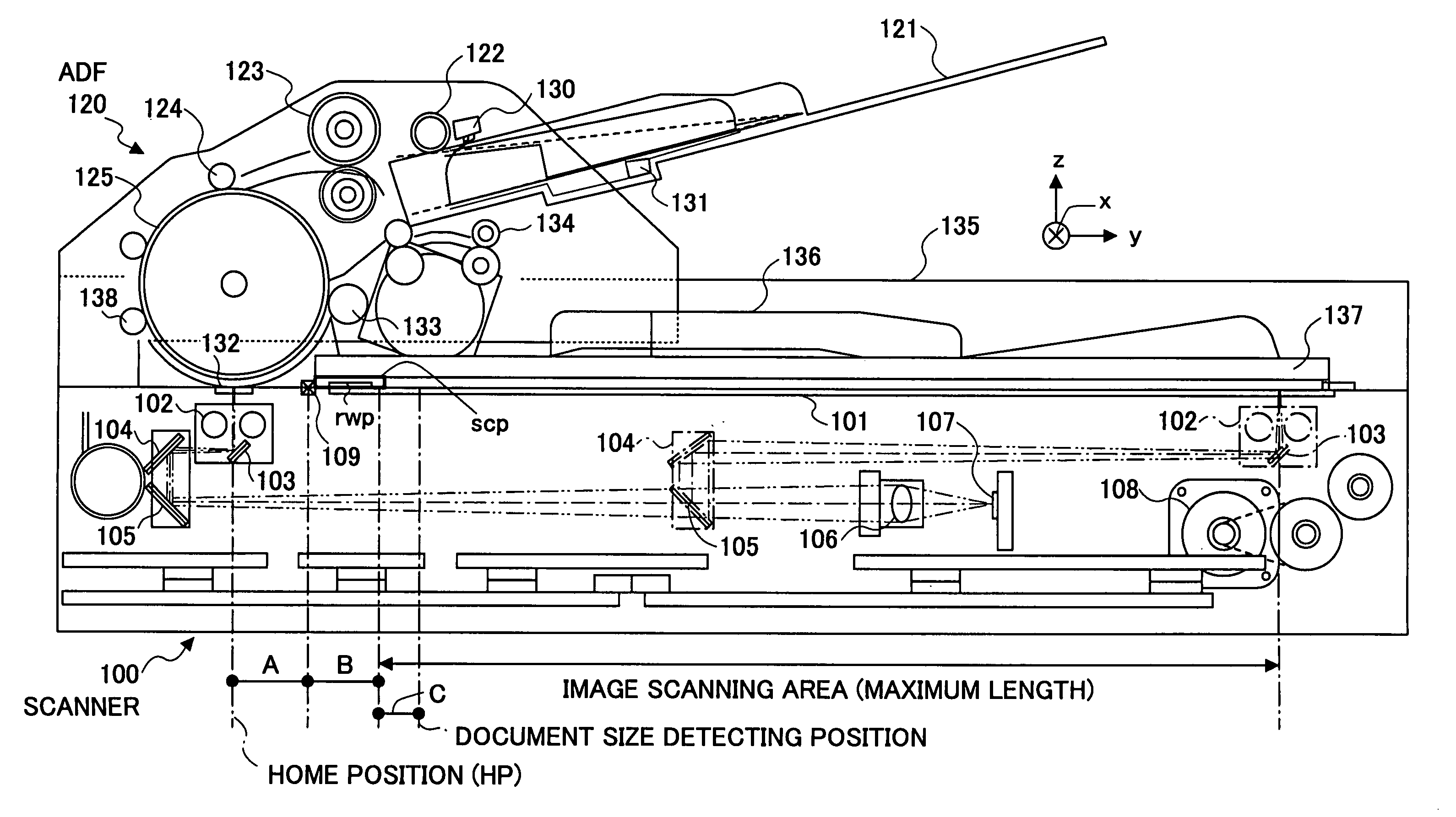
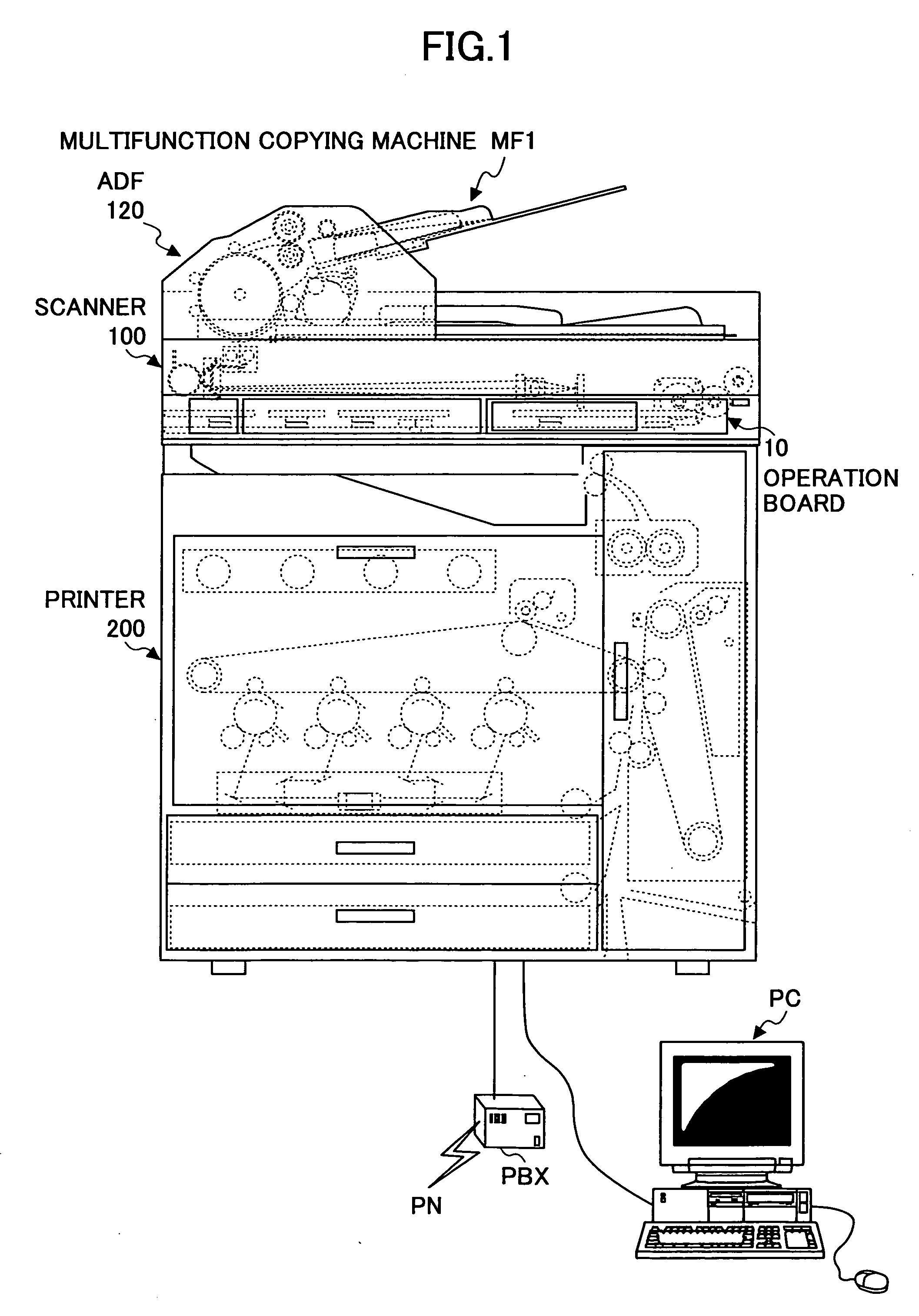
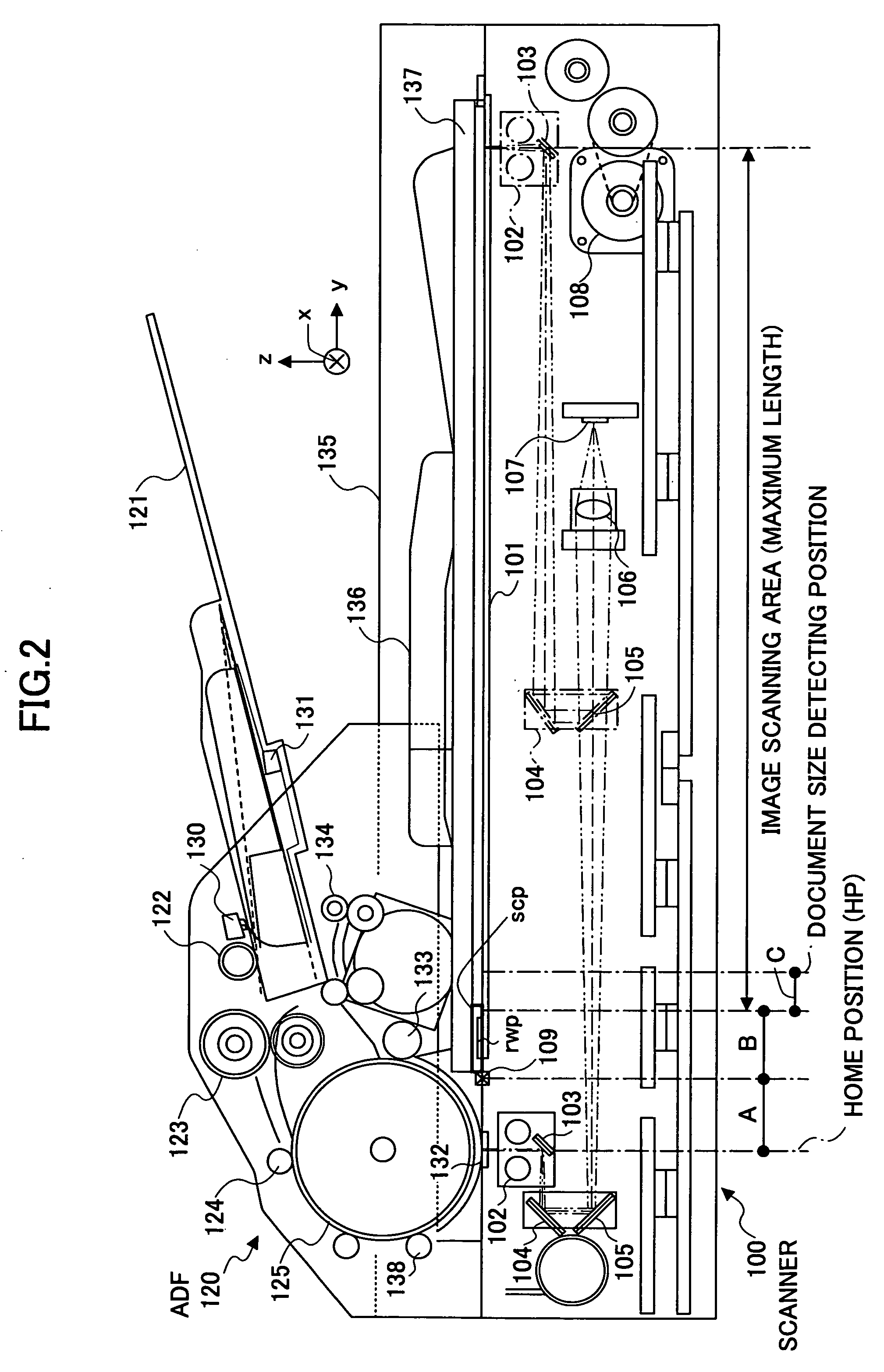
[0100]FIG. 1 is a diagram illustrating a full color digital multifunction copying machine MF1 according to a first embodiment of the present invention. The full color copying machine MF1 according to the present embodiment includes an automatic document feeder (ADF) 120, an operations board 10, a color scanner 100, and a color printer 200, for example. In the illustrated example, the operations board 10 and the color scanner 120 with the ADF 120 attached thereto may be detached from the printer 200. The color scanner 100 includes a control board including a power driver or a sensor input and a controller, for example, and is configured to directly or indirectly establish communication with an engine controller (e.g., CPU 301 of FIG. 5) to have its timing controlled in reading a document image.

[0101] It is noted that in the illustrated example, an engine 300 (see FIG. 5) including the scanner 100, the printer 200, and an image input / output processing apparatus 302 (see FIG. 5) is co...

second embodiment

[0228]FIG. 18 is a diagram showing a configuration of a full color multifunction copying machine MF2 according to a second embodiment of the present invention. The full color multifunction copying machine MF2 of the present embodiment includes an ADF 120, an operations board 10, and a color scanner 100 that are substantially identical to the ADF 120, the operations board 10, and the color scanner 100 of the full color multifunction copying machine MF1 according to the first embodiment. However, a printer 200a of the full color multifunction copying machine MF2 differs from the printer 200 of the full color multifunction copying machine MF1 in that it corresponds to a full color inkjet printer.

[0229] The inkjet printer 200a of the multifunction copying machine MF2 includes a print unit 240 having color ink jet heads arranged at a carriage 241 that is configured to move back and forth in a main scanning direction x. The inkjet heads include C, M, Y, and K ink recording heads arranged...


PUM


Abstract

An image reading apparatus is provided that includes an image sensor configured to convert image light of a document into an image signal, an optical unit configured to project the image light of the document on the image sensor, a drive unit configured to drive the optical unit in a sub scanning direction, a document size detecting unit configured to detect a size of the document using the image signal, an image signal processing unit configured to digitally convert the image signal of the image sensor into image data, a power circuit configured to output an operating voltage in standby mode and stop the outputting of the operating voltage in sleep mode, and a power saving control unit configured to position the optical unit to a document size detecting position before switching the power circuit from the standby mode to the sleep mode.

Description

BACKGROUND OF THE INVENTION [0001] 1. Field of the Invention [0002] The present invention generally relates to an image reading apparatus configured to read a document image by driving an optical system that projects image light of the document on an image sensor in a sub scanning direction. The present invention particularly relates to an image reading apparatus that includes a power saving power circuit and an imaging apparatus using such an image reading apparatus. For example, an image reading apparatus according to an embodiment of the present invention may be used in a document scanner, a digital copier, or a facsimile machine. [0003] 2. Description of the Related Art [0004] In Japanese Laid-Open Patent Publication No. 2004-258386, a flat-bed document scanner is disclosed that is configured to irradiate light on an original document 101 placed on a translucent document table 102 by a panel lamp 103 that is included in a first carriage 105, reflect the reflected light of the do...

Claims


Application Information

Patent Timeline
IPC IPC(8): H04N1/04
CPCH04N1/00708H04N1/00737H04N1/00885H04N1/00896H04N1/1013H04N1/193H04N2201/0094
Inventor HOSHI, KAZUNORI
Owner RICOH KK
Learn More