GMR sensors with strongly pinning and pinned layers

a layer and gmr technology, applied in the field of magnetic transducers, can solve the problems of low tsub>b /sub>, low corrosion resistance, and difficult, or almost impossible, and achieve the effect of optimally biased sensor operation, zero net magnetic moment, and simplified design

Inactive Publication Date: 2006-08-31
WESTERN DIGITAL TECH INC
View PDF26 Cites 32 Cited by
  • Summary
  • Abstract
  • Description
  • Claims
  • Application Information

AI Technical Summary

Benefits of technology

[0054] A method for achieving a nearly zero net magnetic moment of Co—Fe/Ru/Co—Fe pinned layers in the GMR sensor is described in the related application reference above. Al—O/Ni—Cr—Fe/Ni—Fe/Ir—Mn—Cr/Co—Fe/Ru/Co—Fe/Cu—O/Ta films are deposited on a glass substrate. The first pinned layer is varied in thickness while the other pinned layer is held constant in thickness. The nearly zero net areal magnetic moment is determined by plotting a relationship between the net areal magnetic moment and the thickness of the

Problems solved by technology

When the GMR sensor is operating at elevated temperatures in the data storage system, an inadequate exchange coupling can cause canting of the magnetization of the pinned layer from the preferred transverse direction, causing malfunction of the sensor operation.
Hence, it is difficult, or almost impossible, to find a suitable Mn content for either the Co—Fe/Pt—Mn or Co—Fe/Ni—Mn films to attain a high HUA and a high TB simultaneously, as well as desirable corrosion resistance.
However, previous studies indicate that such a high Mn content leads to a low TB

Method used


Image

  • GMR sensors with strongly pinning and pinned layers
  • GMR sensors with strongly pinning and pinned layers
  • GMR sensors with strongly pinning and pinned layers

Examples


Embodiment Construction

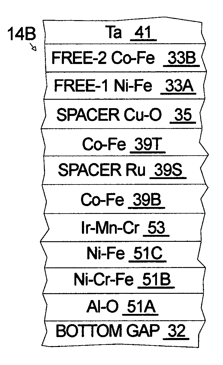
[0072] A bottom-type giant magnetoresistance (GMR) sensor 14B with strongly pinning and pinned layers, as shown in FIG. 7A, is described for magnetic recording at ultrahigh densities according to the invention. The GMR sensor 14B is used in a current-in-plane (CIP) storage system, and can be also used in a current-perpendicular-to-plane (CPP) storage system. The thicknesses shown in the figures are not according to scale. The thickness of the layers are according to the prior art except where note below. The bottom gap layer 32 is preferably an Al2O3 film deposited on the bottom shield layer (not shown). The bottom gap layer 32 is formed according to the prior art and is followed by the seed layers 51 according to the invention. The pinning layer 53 is deposited next and is followed by a first pinned layer 39B, an AP spacer layer 39S and a second pinned layer 39T. The GMR spacer layer 35 separates the second pinned layer 39T from the free (sense) layers 33. The cap layer 41 is depos...


PUM


Abstract

A giant magnetoresistance (GMR) sensor with strongly pinning and pinned layers is described for magnetic recording at ultrahigh densities. The pinning layer is an antiferromagnetic (AFM) iridium-manganese-chromium (Ir—Mn—Cr) film having a Mn content of approximately from 70 to 80 atomic percent and having a Cr content of approximately from 1 to 10 atomic percent. The first pinned layer is preferably a ferromagnetic Co—Fe having an Fe content of approximately from 20 to 80 at % and having high, positive saturation magnetostriction. The second pinned layer is preferably a ferromagnetic Co—Fe having an Fe content of approximately from 0 to 10 atomic percent. The net magnetic moment of the first and second pinned layers is designed to be nearly zero in order to achieve a pinning field of beyond 3,000 Oe.

Description

RELATED APPLICATION [0001] An application entitled “Method of Fabricating Magnetic Sensors with Pinned Layers with Zero Net Magnetic Moment” was filed on Jan. 31, 2005 and has been assigned Ser. No. 11 / 048259. The prior application describes a method to achieve zero net magnetic moment which can be used with the invention described in this application. This referenced application is hereby incorporated by reference in its entirety. The present application is a continuation-in-part of the earlier application. FIELD OF THE INVENTION [0002] The invention relates to the field of magnetic transducers (heads) used for longitudinal recording in data storage systems, and more particularly to giant magnetoresistance (GMR) sensors used in the magnetic transducers, and even more particularly to the materials and structures of the GMR sensors used to strongly pin magnetizations of pinned layers. BACKGROUND OF THE INVENTION [0003] A typical prior art data storage system 10 used for longitudinal ...

Claims


Application Information

Patent Timeline
IPC IPC(8): G11B5/33G11B5/127
CPCB82Y10/00B82Y25/00G11B5/3929G11B2005/3996
Inventor LI, JINSHANLIN, TSANN
Owner WESTERN DIGITAL TECH INC
Why Eureka
Try Eureka