Manufacturing method for worm wheel, and worm gear reducer

a technology manufacturing method, which is applied in the direction of gear teeth, gear teeth, gear manufacturing apparatus, etc., can solve the problems of raising the manufacturing cost difficult to ensure etc., and achieve the effect of ensuring the durability of worm gear reducer, and preventing the meshing portion

Active Publication Date: 2006-09-07
NSK LTD
View PDF3 Cites 13 Cited by
  • Summary
  • Abstract
  • Description
  • Claims
  • Application Information

AI Technical Summary

Benefits of technology

[0043] In general, when the worm gear reducer is used, it is possible to prevent the occurrence of interference of the tip (root) of the operational worm with the root (tip) of the worm wheel in the case where the clearance of the worm gear reducer is positive (>0) relative to a case where the clearance of the worm gear reducer is zero. As a result, it is possible to prevent the meshing portion of the worm with the worm wheel from being locked.
[0044] According to the second aspect of the present invention, it is possible to prevent the tip (root) of the worm wheel after the completion of machining from interfering with the root (tip) of the operational worm. As a result, it is possible to prevent the meshing portion of the worm with the worm wheel from being locked. Further, by the entire meshing portion of the worm wheel with the worm, it is possible to generate a gap between the tip (root) of the worm wheel and the root (tip) of the worm at all times. Therefore, lubricant can easily proceed to a position between the tip (root) of the worm wheel and the root (tip) of the worm. Accordingly, the meshing portion can be lubricated in an excellent condition, and the durability of the worm gear reducer can be sufficiently ensured.

Problems solved by technology

17 to 19) is so small (it leads increase of contact pressure) that it becomes difficult to ensure the durability of the worm gear reducer.
However, when the worm gear reducer is driven being subjected to running-in process as described above, the manufacturing cost of the worm gear reducer is raised.

Method used


Image

  • Manufacturing method for worm wheel, and worm gear reducer
  • Manufacturing method for worm wheel, and worm gear reducer
  • Manufacturing method for worm wheel, and worm gear reducer

Examples


embodiment 1

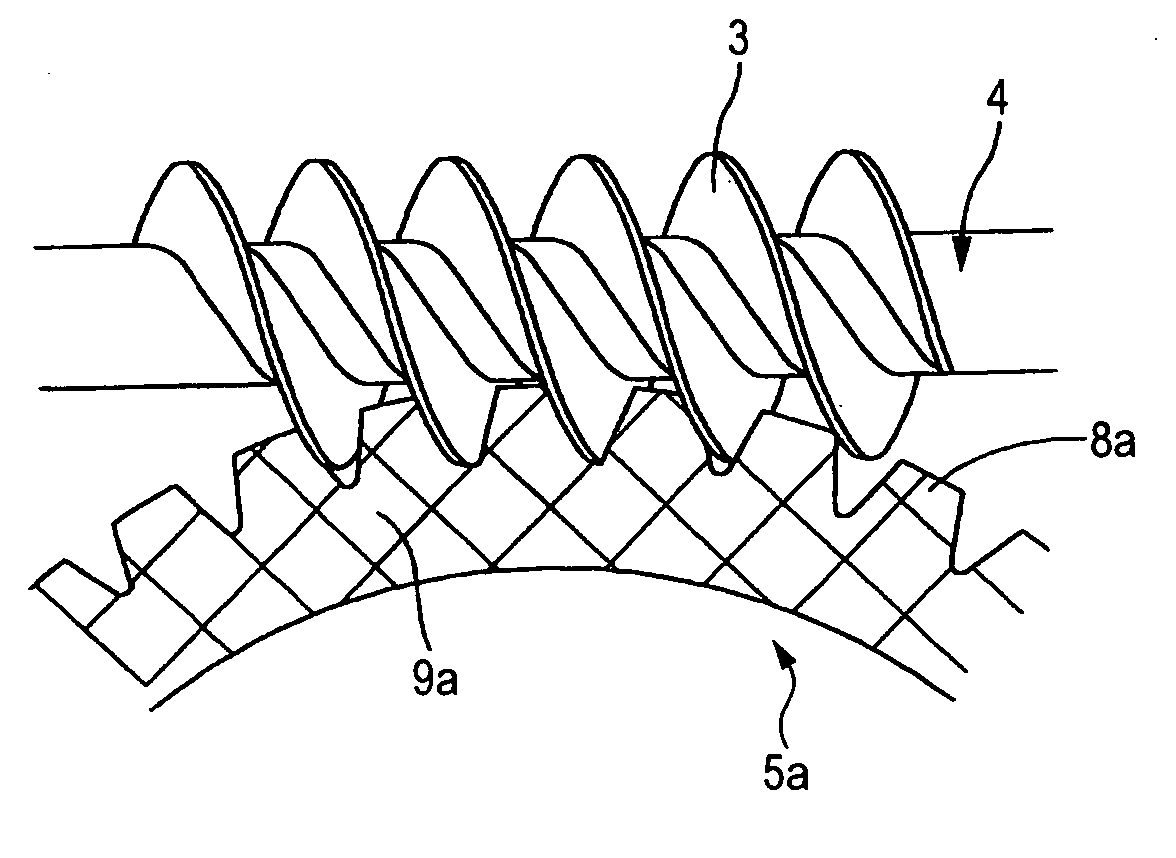
[0079] FIGS. 1 to 6 are views showing Embodiment 1 of the present invention which corresponds to the first and fourth through eighth aspects of the present invention. In this connection, the characteristics of this embodiment are the manufacturing method for a worm wheel 5a and the structure of a worm gear reducer including the worm wheel 5a. The structure and operation of the other portions are the same as those of the conventional structure shown in FIG. 17. Therefore, the duplicated drawings and explanations are omitted or simplified here, and the characteristic portions of this embodiment will be mainly explained as follows.

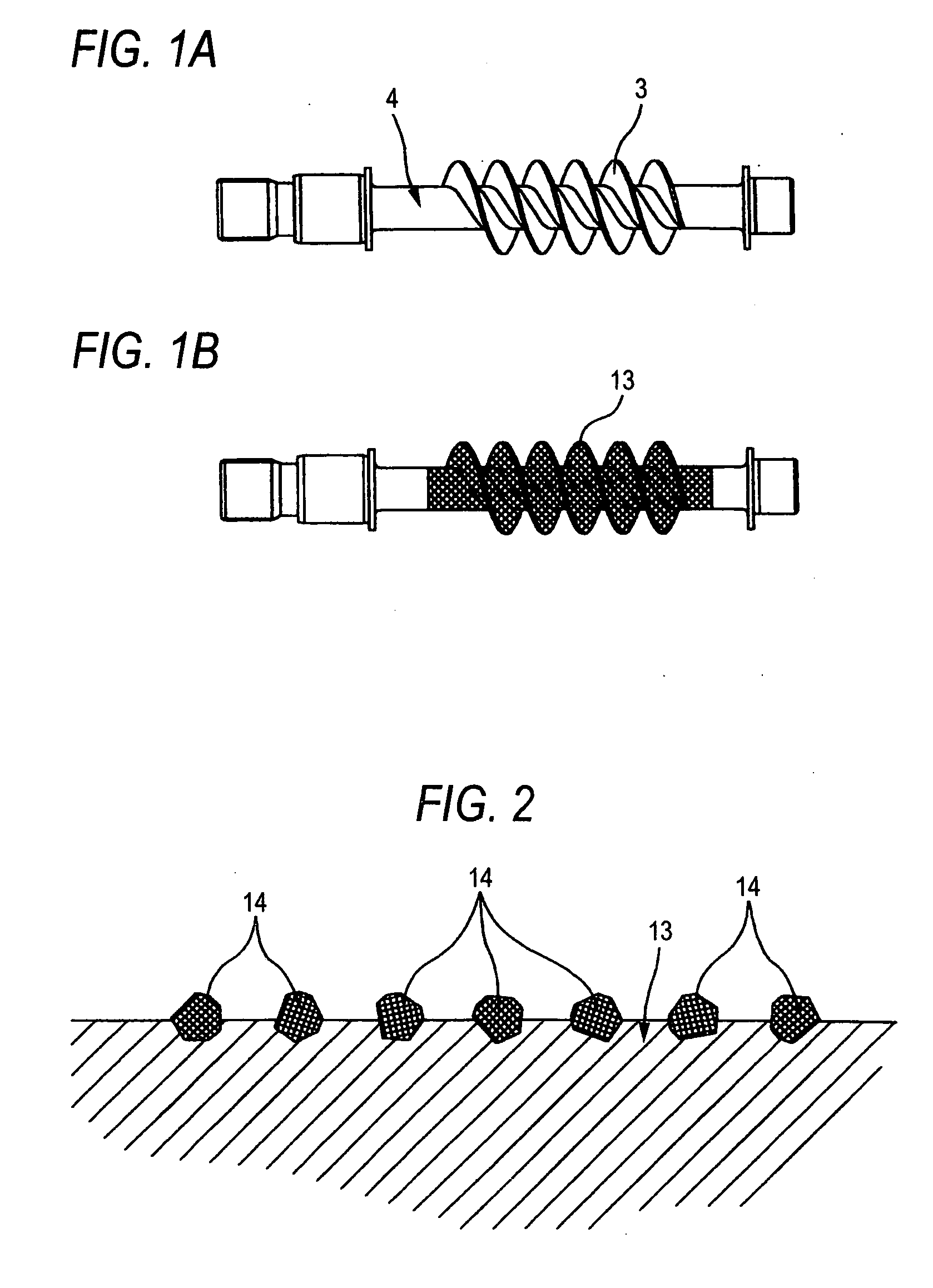
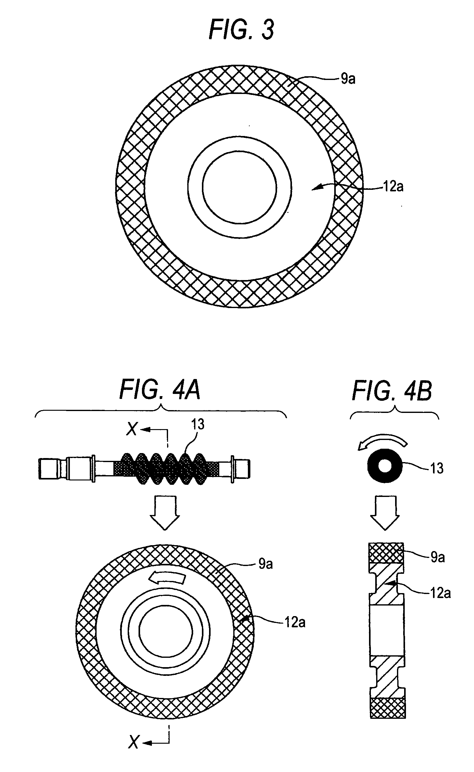
[0080] In this embodiment, as the tool used for machining the tooth portion 8a of the worm wheel 5a, the machining worm 13 shown in FIG. 1B is used. This machining worm 13 is composed in such a manner that a large number of abrasive grains 14, 14 (shown only in FIG. 2) are electro-deposited on the surface thereof, of which shape and size are the same as thos...

embodiment 2

[0089] FIGS. 7 to 11 are views showing Embodiment 2 of the present invention which corresponds to the first and fourth through eighth aspects of the present invention. In this embodiment, concerning the tool used for machining the tooth portion 8b of the worm wheel 5b, the machining worm 13a shown in FIG. 7B is used. This machining worm 13a is composed in such a manner that a large number of abrasive grains 14, 14 (shown in FIG. 2) are electro-deposited on the surface of the worm, the shape and size of which are the same as those of the operational worm 3 meshed with the tooth portion 8b of the worm wheel at the time of use as shown in FIGS. 7A and 11. In this connection, the fine hatched portions (which can be seen as if they were painted out black) shown in FIG. 7B, is a portion in which a large number of abrasive grains 14, 14 are electro-deposited. Due to the foregoing, the portion, on which a large number of abrasive grains are electro-deposited in the machining worm 13a, is ma...

embodiment 3

[0094]FIGS. 12 and 13 are views showing Embodiment 3 of the present invention which corresponds to the first and fourth through eighth aspects of the present invention. In the case of Embodiment 1 described before, an object to be manufactured is the worm wheel 5a which is meshed with the cylindrical operational worm 3. On the other hand, in this embodiment, as shown in FIG. 13, an object to be manufactured is the worm wheel 5c which is meshed with the middle-recessed drum worm 3a. In this embodiment, in the same manner as that of Embodiment 1 described before, the machining worm 13b shown in FIG. 12B is composed in such a manner that a large number of abrasive grains 14, 14 (shown in FIG. 2) are electro-deposited on a surface of the middle-recessed drum worm, the shape and size of which are the same as those of the operational worm 3a at the time of use shown in FIGS. 12A and 13. In this connection, the fine hatched portion (which can be seen as if they were painted out black) show...


PUM

PropertyMeasurementUnit
surface roughnessaaaaaaaaaa
sizeaaaaaaaaaa
sizeaaaaaaaaaa

Abstract

A manufacturing method for a worm wheel, the worm wheel meshed with an operational worm at usage, has steps of preparing a worm wheel, in which at least a surface layer of a tooth portion is made of synthetic resin, preparing a machining worm, in which pitch of teeth of the machining worm in an axial direction thereof is the same as that of an operational worm, diameters of tip and root portions of the tooth of the machining worm are equal to or more than those of the operational worm and abrasive grains are provided on a surface of the machining worm by means of electro-deposition, disposing the machining worm in a twisting position relative to the worm wheel and rotating the machining worm and the worm wheel with meshing each other so as to machining the tooth portion of the worm wheel.

Description

[0001] The present invention claims foreign priority to Japanese patent application No. 2004-332322, filed on Nov. 16, 2004, the contents of which is incorporated herein by reference. BACKGROUND OF THE INVENTION [0002] 1. Field of the Invention [0003] The present invention relates to a worm gear reducer which is used being incorporated into an electric power steering device, a nursing bed and so forth. The present invention also relates to a manufacturing method for a worm wheel composing the worm gear reducer. [0004] 2. Description of the Background Art [0005] In order to reduce a force needed for operating a steering wheel when a driver gives a steering angle to vehicle wheels to be steered (Vehicle wheels to be steered are usually front wheels except for a special vehicle such as a forklift), a power steering device is generally used. As for this power steering device, an electric power steering device, in which an electric motor is used as an assisting power source, has recently...

Claims


Application Information

Patent Timeline
Patent Type & Authority Applications(United States)
IPC IPC(8): F16H1/16
CPCB23F11/00Y10T74/19828F16H55/22B23F21/026
Inventor MAEDA, ATSUSHICHIKARAISHI, KAZUO
Owner NSK LTD
Why Eureka
Try Eureka