Blow-by gas and purge gas treating device in intake valve lift variable engine

Inactive Publication Date: 2006-09-07
HONDA MOTOR CO LTD
View PDF7 Cites 37 Cited by
  • Summary
  • Abstract
  • Description
  • Claims
  • Application Information

AI Technical Summary

Benefits of technology

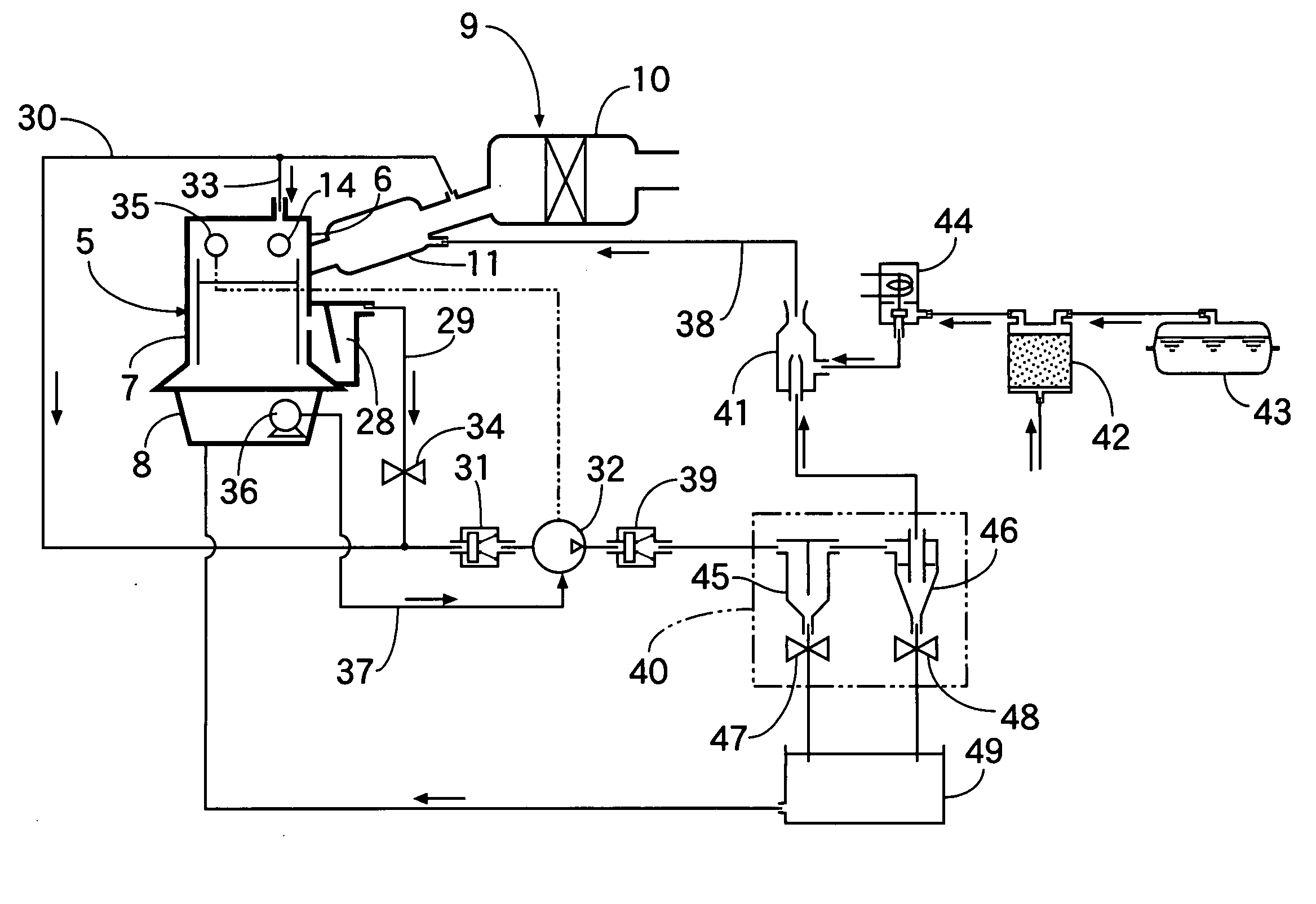
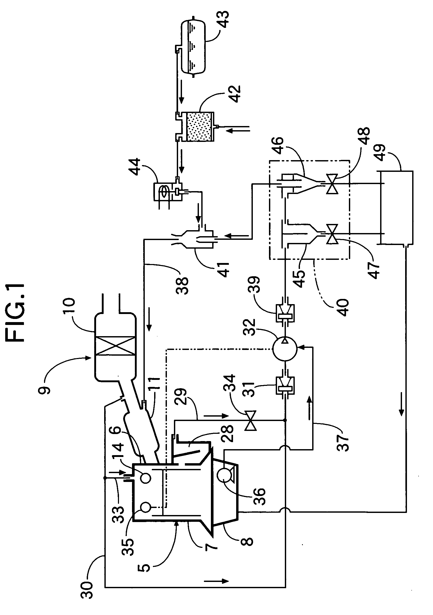
[0013] According to a fifth feature of the present invention, in addition to the first feature, a first intake pipe line for guiding the blow-by gas from the crank case and a second intake pipe line having one end connected to the intake system and bypassing the engine body are connected to the intake side of the first pump. With the fifth feature, communication resistance in a communication path of the blow-by gas in the engine body is varied according to the difference in internal structure of the engine body, but by connecting the first intake pipe line for guiding the blow-by gas from the crank case and the second intake pipe line bypassing the engine body to the first pump and by sucking the blow-by gas and new air with the first pump, a flow rate can be easily regulated so that a sufficient amount of gas can be sucked by the first pump despite the difference in the structure of the engine body, and gas for generating a sufficient negative pressure can be pressurizingly transferred by the first pump even if a jet pump is used as the second pump.
[0014] According to a sixth feature of the present invention, in addition to the first feature, the first pump is operable in association with and connected to an exhaust-side camshaft. With the sixth feature, in the non-throttle operation in which the amount of intake air is regulated by opening/closing control of the intake valve, there is not a sufficient space on the intake valve side since a control device of the intake valve is disposed on the intake valve side, but a space for disposing a driving system of the first pump can be easily secured by driving the first pump with an exhaust-side camshaft.
[0015] According to a seventh feature of the present invention, in addition to the second feature, an oil passage for guiding oil from an oil pump provided on the engine body is connected to the first pump for lubrication of the first pump. With the seventh feature, the oil is supplied to the first pump from an oil pump originally attached to the engine body for supplying the oil to each of lubrication portion

Problems solved by technology

Therefore, in the intake valve lift variable engine disclosed in the Japanese Patent Application Laid-open No. 2005-9487, generation of a negat

Method used


Image

  • Blow-by gas and purge gas treating device in intake valve lift variable engine
  • Blow-by gas and purge gas treating device in intake valve lift variable engine
  • Blow-by gas and purge gas treating device in intake valve lift variable engine

Examples


Example

[0024] A first embodiment of the present invention will be described referring to FIGS. 1 to 3. As shown in FIG. 1, an intake system 9 has an air cleaner 10 for purifying air from the outside and an intake chamber 11 connected to the air cleaner 10 on the downstream side, and is connected to a cylinder head 6 of an engine body 5. No throttle valve is provided in this intake system 9.

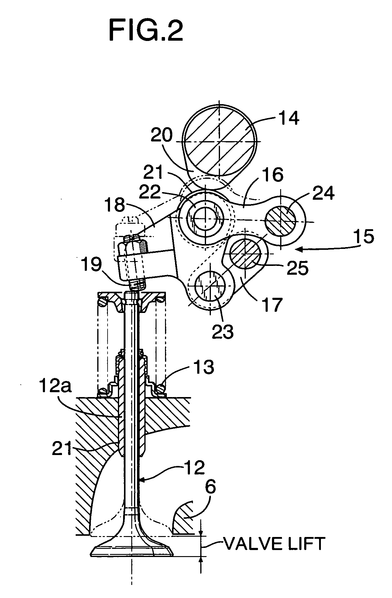
[0025] In FIG. 2, an intake valve 12 is disposed on the cylinder head 6 to be capable of opening / closing operation while being urged by a valve spring 13 in the valve-closing direction, and the intake valve 12 is driven by an intake-side camshaft 14 via a lift variable mechanism 15. The lift variable mechanism 15 has a first link arm 16, a second link arm 17 arranged below the first link arm 16, and a rocker arm 18.

[0026] A tappet screw 19 is screwed into one end of the rocker arm 18 to be adjustable in the advanced / retreating positions such that the tappet screw 19 contacts from above with an upper en...

Example

[0047] A second embodiment of the present invention will be described referring to FIG. 4. It is possible to regulate an amount of intake air by changing a lift amount of the intake valve 12 as in the first embodiment (see the first embodiment), and thus it is not necessary to provide a throttle valve for regulating the amount of intake air in the intake system 9.

[0048] Moreover, one end of a first intake pipe line 50 is connected to the breather chamber 28 provided in the crank case of the engine body 5. A control valve 51 is provided at an intermediate portion of the first intake pipe line 50. One end of a second intake pipe line 53 is connected to the purge control valve 44 for discharging as a purge gas the evaporated fuel adsorbed in the canister 42 out of the canister 42 together with external air drawn in from the bottom portion of the canister 42. A control valve 52 is provided at an intermediate portion of the second intake pipe line 53. The other ends of the first and sec...


PUM


Abstract

In an intake valve lift variable engine including: an engine body; a cylinder head; an intake valve which is disposed in the cylinder head and which is controlled to be open and close so as to regulate the amount of intake air; and an intake system having no throttle valve and connected to the cylinder head, blow-by gas is sucked from a crank case of the engine body into a first pump and pressurizingly transferred by the first pump to the side of the intake system, and purge gas from a canister is mixed into the blow-by gas pressurizingly transferred by the first pump. Thus, the blow-by gas and the purge gas are guided to the intake system.

Description

RELATED APPLICATION DAT [0001] The present invention is based upon Japanese priority application Nos. 2005-55473 and 2005-55474, which are hereby incorporated in their entirety herein by reference. BACKGROUND OF THE INVENTION [0002] 1. Field of the Invention [0003] The present invention relates to an intake valve lift variable engine comprising: an engine body; a cylinder head; an intake valve which is disposed in the cylinder head and which is controlled to be open and close so as to regulate the amount of intake air; and an intake system having no throttle valve and connected to the cylinder head, and particularly to a device for treating blow-by gas from a crank case and purge gas purged from a canister. [0004] 2. Description of the Related Art [0005] The Japanese Patent Application Laid-open No. 2005-9487 discloses an intake valve lift variable engine in which a throttle valve is not interposed in an intake system by regulating the amount of intake air sucked by opening / closing ...

Claims


Application Information

Patent Timeline
IPC IPC(8): F02M25/06F02M33/04
CPCF01M13/04F01M2013/0072F01M2013/026F01M2013/0427F01M2013/0433F02M25/06F02M25/08Y02T10/121Y02T10/12
Inventor KAKIMOTO, KAZUHITOSATO, HISASHI
Owner HONDA MOTOR CO LTD
Why Eureka
Try Eureka