

Pin Closure System
- Summary
- Abstract
- Description
- Claims
- Application Information
AI Technical Summary
Benefits of technology
Problems solved by technology
Method used
Image

Examples
Embodiment Construction
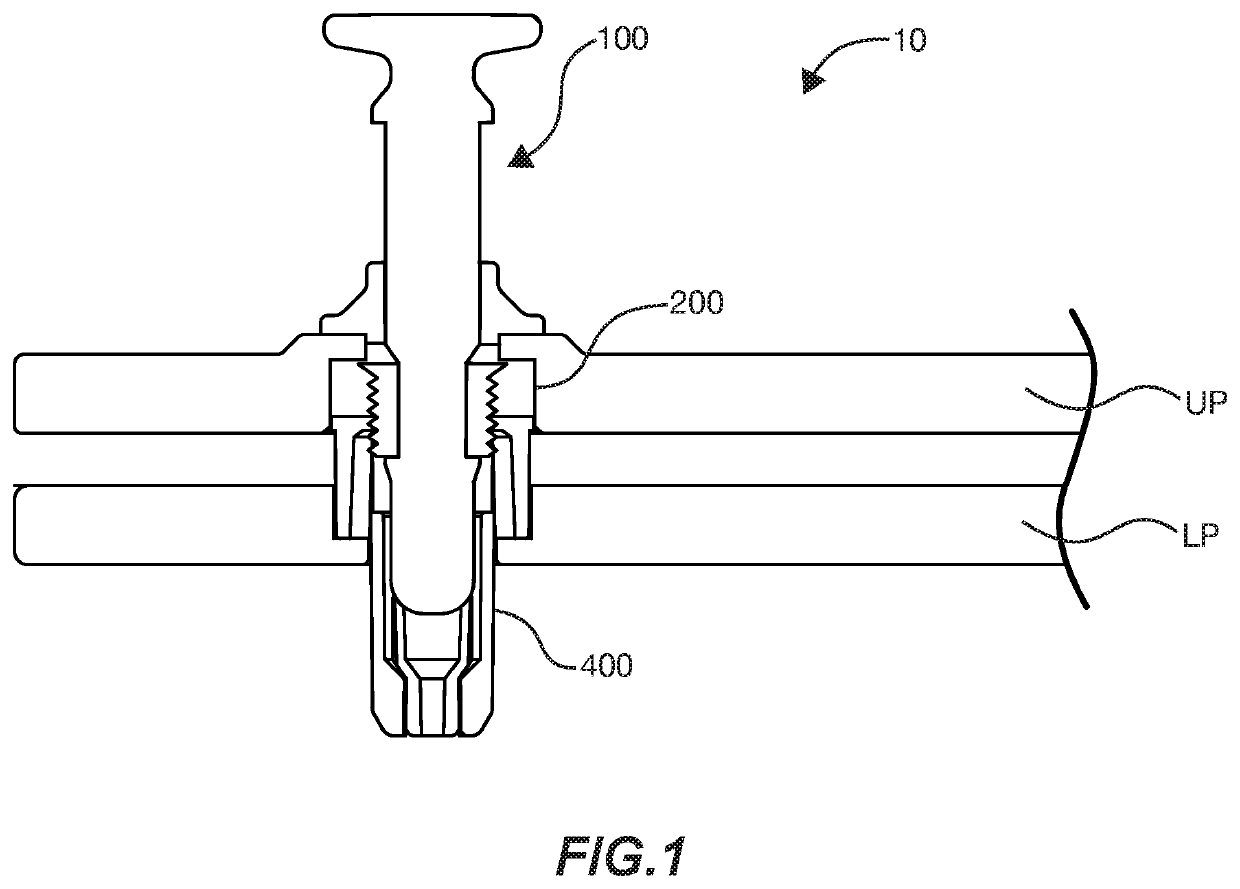
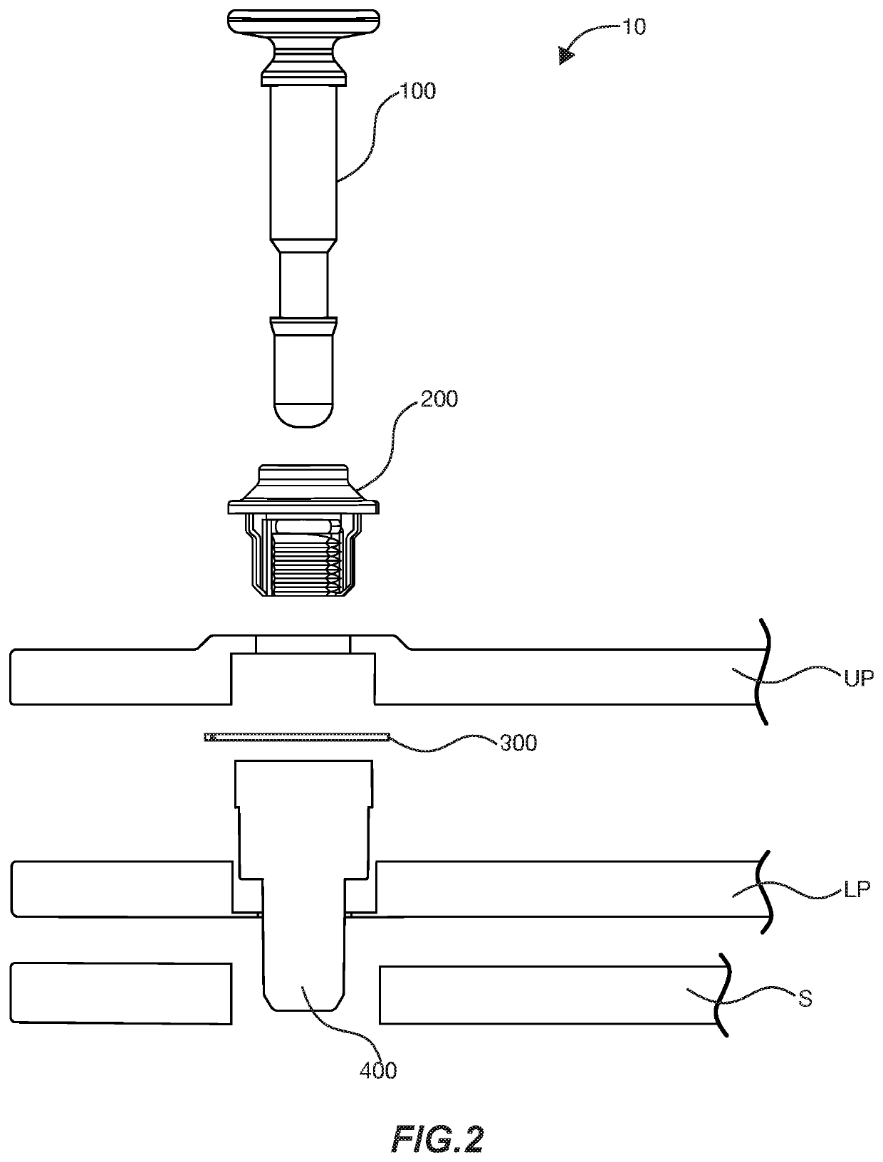
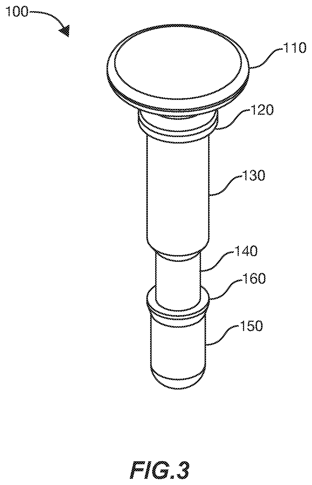
[0029]As seen well in FIGS. 1-8, the system (10) may be used to reversibly secure an upper (UP) and a lower plate (LP), particularly the upper and lower frame plates of a radiation therapy mask, and then further to another substrate (S), such as a treatment board, as seen well in FIGS. 1 and 2. In this specification, the term proximal shall mean those portions of the system (10) that are closer to a user's grip at a pin grip (110), relative to those portions which are further from a user's grip, which shall be deemed distal.
[0030]What is claimed then, is a pin closure system (10), having, among other components, a pin (100), with at least a pin grip (110) and at least one pin diameter (150). The system further includes an upper sleeve (200), seen well in FIGS. 2, 4, 5 and 6, having an upper sleeve barrel portion (240) and an upper sleeve central fenestration (210) reversibly receiving at least a portion of the pin (100). There may be an upper sleeve bearing collar (230) having an up...
PUM
| Property | Measurement | Unit |
|---|---|---|
| Thickness | aaaaa | aaaaa |
| Diameter | aaaaa | aaaaa |
| Expansion enthalpy | aaaaa | aaaaa |
Abstract
Description
Claims
Application Information