
Use of distributed temperature sensors during wellbore treatments

a temperature sensor and wellbore technology, applied in the field of hydrocarbonbearing formation treatment methods, can solve the problems of affecting the treatment effect of wellbore tubular components, affecting the treatment effect, and reacting too quickly

Inactive Publication Date: 2006-09-07
SCHLUMBERGER TECH CORP
View PDF21 Cites 31 Cited by
  • Summary
  • Abstract
  • Description
  • Claims
  • Application Information

AI Technical Summary

Benefits of technology

This patent describes a new way to monitor fluid placement, diverter effectiveness, and fracturing parameters during well treatments in real-time. It uses distributed temperature sensors on an optical fiber or an array of Fiber Bragg Grating temperature sensors to measure temperature and pressure along the fiber during the treatment. This allows for real-time adjustments to be made and ensures the treatment is effective. The fiber can be positioned in the well using coiled tubing or other tools, and it can be easily removed at the completion of the service. The temperature and pressure profiles can be used to determine where the fluid stage entered the formation, and fracturing can also be monitored in real-time to make adjustments and ensure a successful well treatment.

Problems solved by technology

With mineral acids, the major drawback is that they react too quickly and hence penetrate (as unspent acid) into the formation poorly.
Second, they are highly corrosive to wellbore tubular components.
Emulsified acid systems and foamed systems are other commercially available responses to the diversion problem, but they are fraught with operational complexity which severely limits their use—e.g., the flow rates of two different fluids, and the bottom hole pressure must be meticulously monitored during treatment.
They are usually very sensitive to any feature in the reservoir that will conduct these diverting agents out of the target zone, for instance a natural fracture and they may actually damage the formation and create rather than solve matrix damages if used improperly.
The design of a matrix treatment is consequently very challenging.
Hence, the effectiveness of a treatment, and more particularly the diversion effectiveness, is very difficult to evaluate.
During fracture treatments, analysis of surface treating pressures can be used in some cases to analyze it; however, this method does not work for acidizing since pressure surges at the surface may not be correlated to changes in flow profile downhole (see C. W. Crowe, Evaluation of Oil Soluble Resin Mixtures as Diverting Agents for Matrix Acidizing, SPE 3505, 1971 and J. W. Burman, B. E. Hall, Foam as Diverting Technique for Matrix Sandstone Stimulation, SPE 15575, 1986).
As a result methods for determining actual fluid placement have mainly been limited to post treatment analysis.
One main disadvantage of using post treatment analysis to determine fluid entry is that nothing can be done to change things once the treatment is done.

Method used


Image

  • Use of distributed temperature sensors during wellbore treatments
  • Use of distributed temperature sensors during wellbore treatments
  • Use of distributed temperature sensors during wellbore treatments

Examples


Embodiment Construction

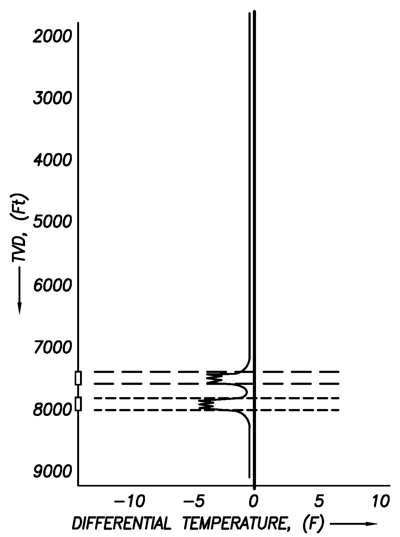
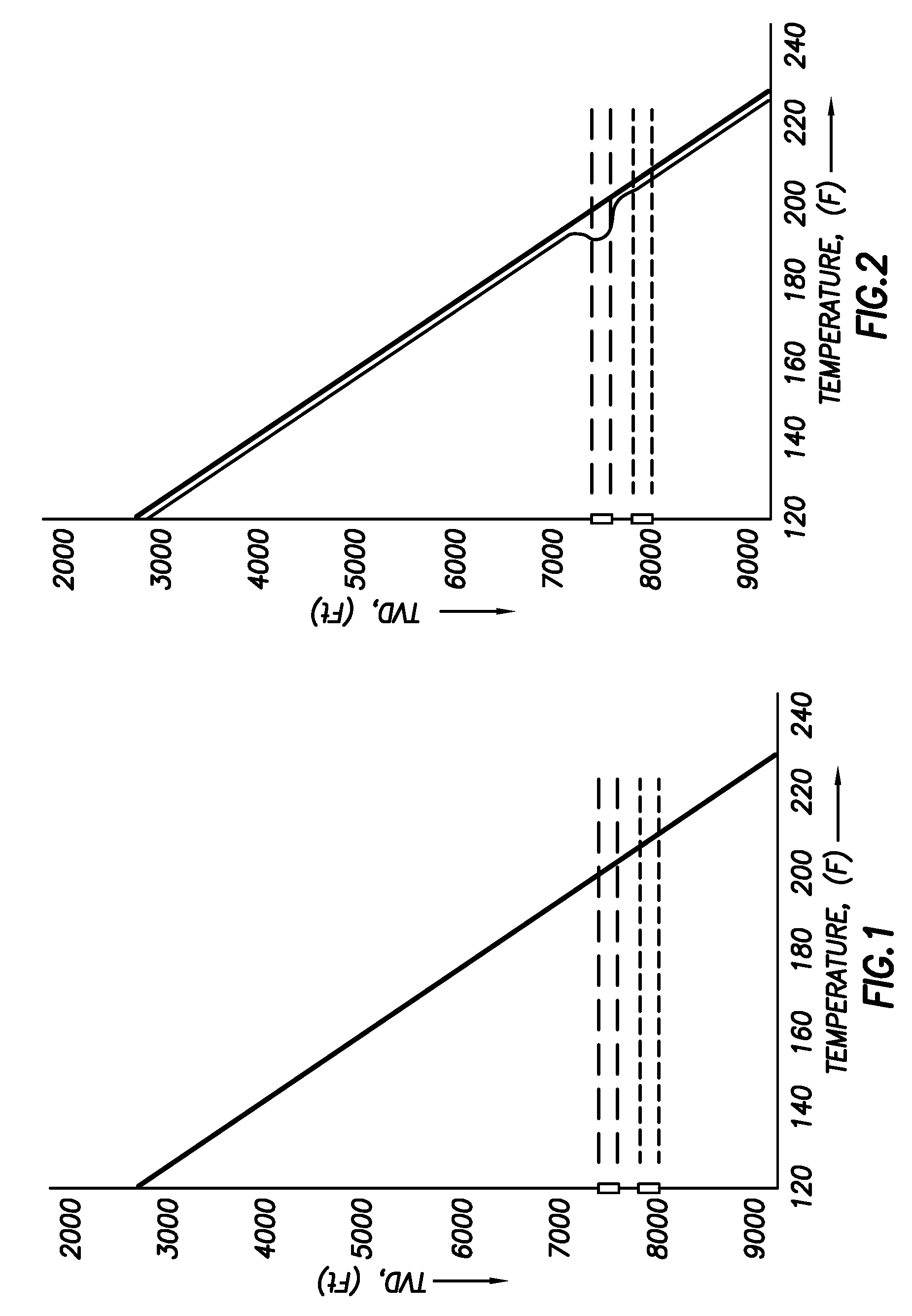
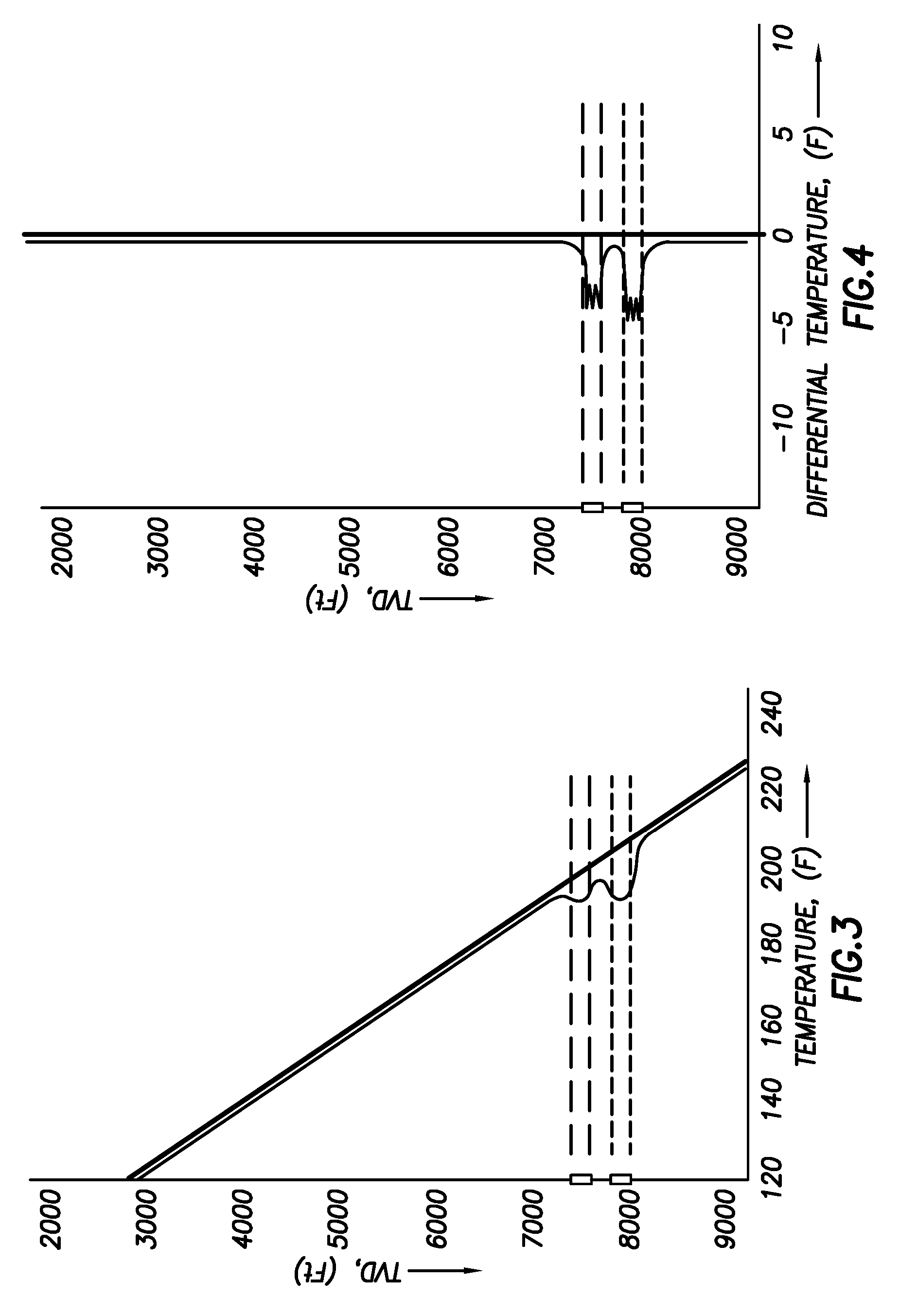
[0029] Analysis of differential temperature logs has been used in the oil and gas industry since the late 1960's as related in SPE 1750—Tracing Fluid Movements with a New Temperature Technique, E. Johns, 1967 and SPE 1977—Some Applications of Differential Temperature Logging, L. R. Jameson. However, this method is rarely used, possibly because it requires well logging both before and after the treatment. Today, a more typical method of determining fluid entry is the use of radioactive (RA) tracers.

[0030] The distributed temperature sensing (DTS) technology was pioneered in the early 1980's. It is based on optical time-domain reflectometry (OTDR), which is used extensively in telecommunications cable testing. Application in the oil and gas industry to date has been as permanent installations (see SPE 71676—The Use of Fiber-Optic Distributed Temperature Sensing and Remote Hydraulically Operated Interval Control Valves for the Management of Water Production in the Douglas Field, M. To...


PUM

PropertyMeasurementUnit
temperatureaaaaaaaaaa
pressureaaaaaaaaaa
permeabilityaaaaaaaaaa

Abstract

The invention relates to a method for treating subterranean formation comprising providing distributed temperature sensors, injecting a treatment fluid and monitoring the temperature across the treatment interval during the injection process.

Description

CROSS REFERENCE TO RELATED APPLICATIONS [0001] This is a Utility Application of prior pending provisional patent application Ser. No. 60 / 403,865 filed Aug. 15, 2002.TECHNICAL FIELD OF THE INVENTION [0002] This Invention is directed to methods for treating hydrocarbon-bearing formations—i.e., to increase the production of oil / gas from the formation. More specifically, the invention relates to the placement of fluids for instance for stimulation treatment such as matrix and fracture treatments. BACKGROUND AND PRIOR ART [0003] Hydrocarbons (oil, natural gas, etc.) are obtained from a subterranean geologic formation (i.e., a “reservoir”) by drilling a well that penetrates the hydrocarbon-bearing formation. This provides a partial flowpath for the oil to reach the surface. In order for oil to be “produced,” that is, travel from the formation to the wellbore, and ultimately to the surface, there must be a sufficiently unimpeded flowpath from the formation to the wellbore. If the formation...

Claims


Application Information

Patent Timeline
Patent Type & Authority Applications(United States)
IPC IPC(8): E21B47/00E21B47/07C12N13/00C12N15/02E21B43/26G01D5/353G01K11/32G06F19/00H04L29/06
CPCC12N13/00C12N15/02E21B43/26E21B47/065E21B47/122G01D5/35383G01K11/32G06F19/20G06F19/24H04L29/06027G16B25/00G16B40/00E21B47/07E21B47/13E21B43/27E21B43/16E21B47/12H04L65/1101
Inventor JEE, VIRGINIAFLAMANT, NICOLASTHOMEER, HUBERTUSADNAN, SARMADGAY, MICHAEL
Owner SCHLUMBERGER TECH CORP
Learn More