Transformer with protection against direct current magnetization caused by zero sequence current

a transformer and direct current technology, applied in the direction of transformer/inductance details, instruments, electrical equipment, etc., can solve the problems of transformers consuming high magnetizing currents, transformers entering magnetic saturation, disturbances in the transmission and distribution of electrical energy, etc., to eliminate high magnetization saturation levels and high impedance

Inactive Publication Date: 2006-09-07
FORSKARPATENT I SYD AB
View PDF16 Cites 31 Cited by
  • Summary
  • Abstract
  • Description
  • Claims
  • Application Information

AI Technical Summary

Benefits of technology

[0005] It has turned out possible to introduce a passive compensation system of direct current, zero sequence current, induced by geomagnetic field changes in transformers eliminating high magnetization saturation levels, which is characterize...

Problems solved by technology

The direct current gives rise to unilateral magnetization levels of any transformer in the system, which may cause the core of the transformer to enter magnetic saturation.
This leads to the transformer consuming high magnetizing currents, thus being disc...

Method used


Image

  • Transformer with protection against direct current magnetization caused by zero sequence current
  • Transformer with protection against direct current magnetization caused by zero sequence current
  • Transformer with protection against direct current magnetization caused by zero sequence current

Examples


first embodiment

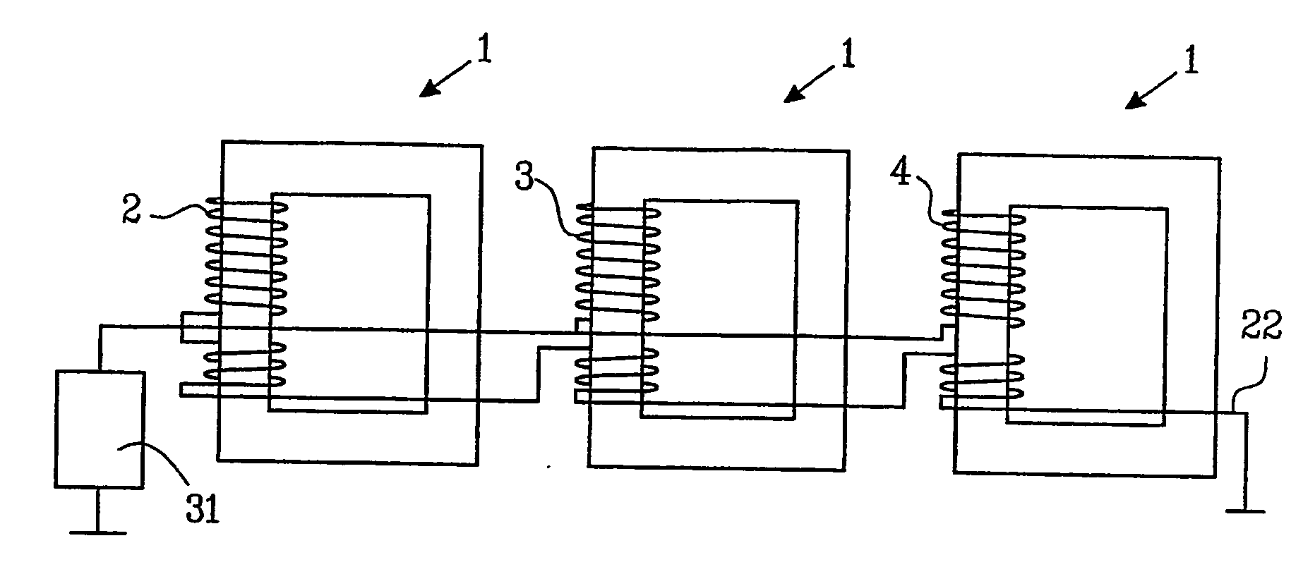
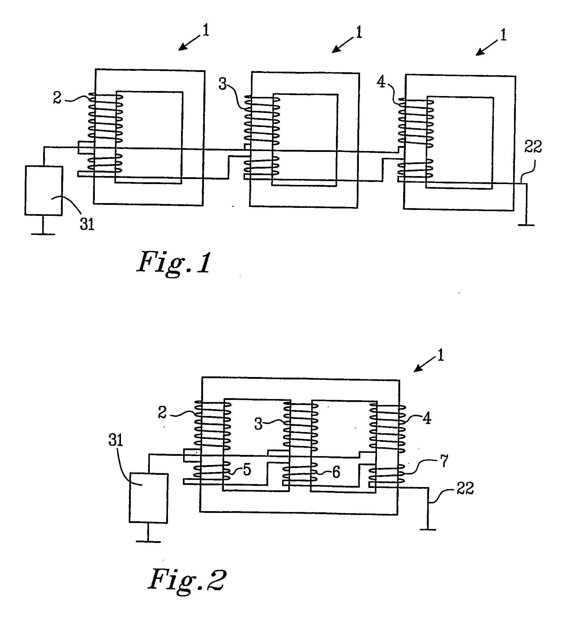
[0021] the invention shows (FIG. 2) a three-phase transformer 1 comprising three phase windings 2, 3, 4 one for each phase on each their leg, whereby the phase windings are separated in a primary winding and a secondary winding on each leg. The construction of primary versus secondary winding does not matter with the regard to the present invention, and these have been separated one over the other in the drawings, whereby alternatives are the one outside the other depending on the parameters to be chosen for the specific use of the transformer. Three compensation windings 5, 6, 7 connected in series (one for each phase leg) are present on the transformer 1, whereby the transformer has no magnetic return conductor. The compensation windings 5, 6, 7 are all, preferably wound in a direction opposite the ones of the main phase windings 2, 3, 4, however, the direction of their winding turns, in this embodiment is not critical due to the control of this transformer embodiment.
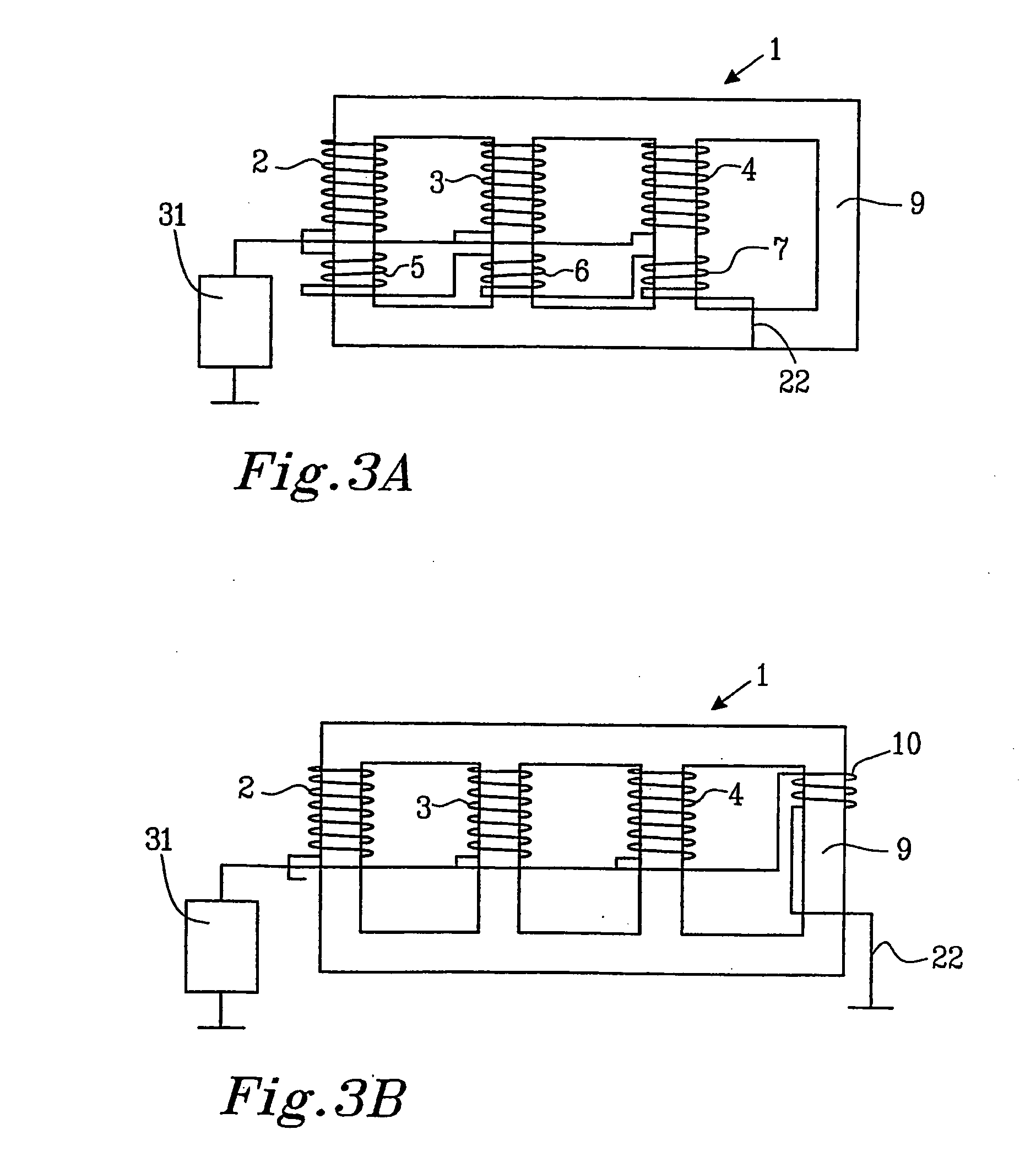
[0022]FIG. 3...


PUM


Abstract

The present invention relates to a transformer being protected against direct current induced by geomagnetic flux changes, so called zero sequence current, whereby it comprises at least one compensation winding for direct current on the transformer core to compensate for undesired magnetization, by adding a current opposite to the direction of the magnetization caused by the zero sequence current carried by the alternating current to be transformed to reduce high magnetization saturation levels.

Description

TECHNICAL FIELD [0001] The present invention relates to a transformer with protection against direct current magnetization caused by zero sequence current, in a power generation, transmission or distribution system with a rated power ranging from a few kVA up to more than 1000 MVA and with a rated voltage ranging from 3-4 kV and up to very high transmission voltages, 400 kV to 800 kV or higher. BACKGROUND OF THE INVENTION. [0002] The primary task of a power transformer is to act as an electric “gear box” and sometimes to create a galvanic isolation, allowing electric energy to flow from one electrical system to another. The electrical systems interconnected with a transformer usually have different voltages but always the same frequency. The power transformer, in its simplest form, comprises generally at least two windings, a primary winding and a secondary winding. The transformation ratio is defined by the winding turns in the primary and secondary winding and the connection of th...

Claims


Application Information

Patent Timeline
IPC IPC(8): H02H7/10H01F27/38H01F27/40H01F30/12
CPCH01F27/38H01F27/402H01F30/12
Inventor AF KLERCKER ALAKULA, MATS
Owner FORSKARPATENT I SYD AB
Why Eureka
Try Eureka