Camera module and the manufacturing process thereof

a technology of camera modules and manufacturing processes, applied in the field of high heat-resistant camera modules, can solve the problems of not being able to use the smt assembly process to assemble the camera modules b>11, and the traditional camera modules b>11/b> may not be provided

Inactive Publication Date: 2006-09-07
PREMIER IMAGE TECH
View PDF15 Cites 42 Cited by
  • Summary
  • Abstract
  • Description
  • Claims
  • Application Information

AI Technical Summary

Benefits of technology

[0008] The present invention provides a camera module comprising a lens, a lens holder, the lens and the lens holder engaged with each other, and an image sensor board located under the lens holder. The lens is formed from a highly heatproof material, preferably sustaining with more than 180° C.—the high temperature requirements of SMT soldering equipment. The highly heatproof material of the lens may be a ceramic, a highly heatproof glass, or the like. Additionally, because the lens holder of the present invention must also sustain with high temperature requirements of SMT soldering equipment, the lens holder is formed of a highly heatproof material, such as liquid crystal polymer (LCP), nylon, or the like. In addition, the image sensor board is typically made by SMT, so it can sustain the high temperatures of SMT soldering equipment.

Problems solved by technology

However, the traditional camera module 11 is not heatproof, and so surface mount technology (SMT), which uses high-heat soldering equipment, cannot be used to assemble the camera module 11 with the main board 12.
As a result, the traditional camera module 11 may be not provided for SMT assembly process and neither to achieve mass production.

Method used


Image

  • Camera module and the manufacturing process thereof
  • Camera module and the manufacturing process thereof
  • Camera module and the manufacturing process thereof

Examples


Embodiment Construction

[0018] The following descriptions of the preferred embodiments are provided to help understand the features and structures of the present invention.

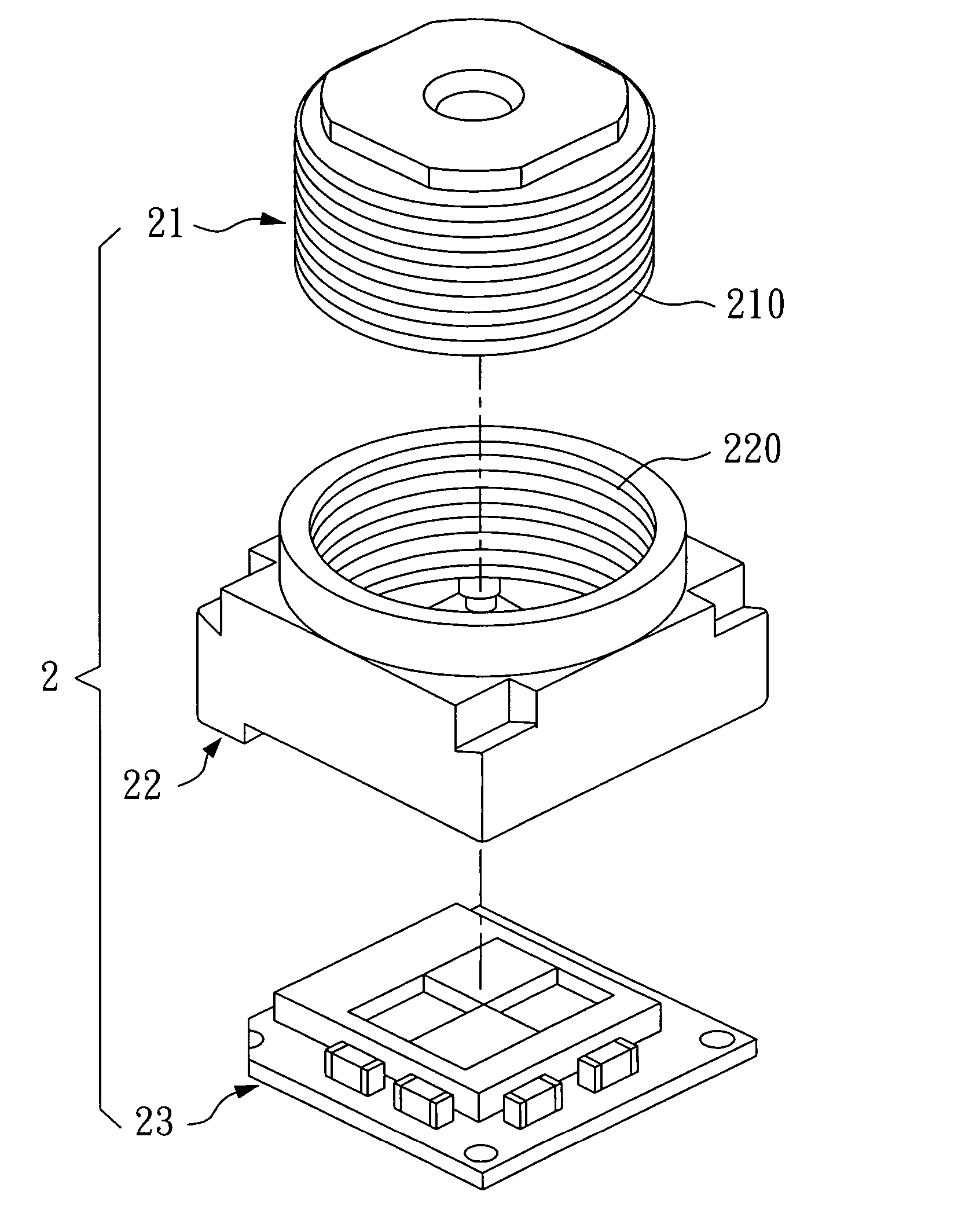
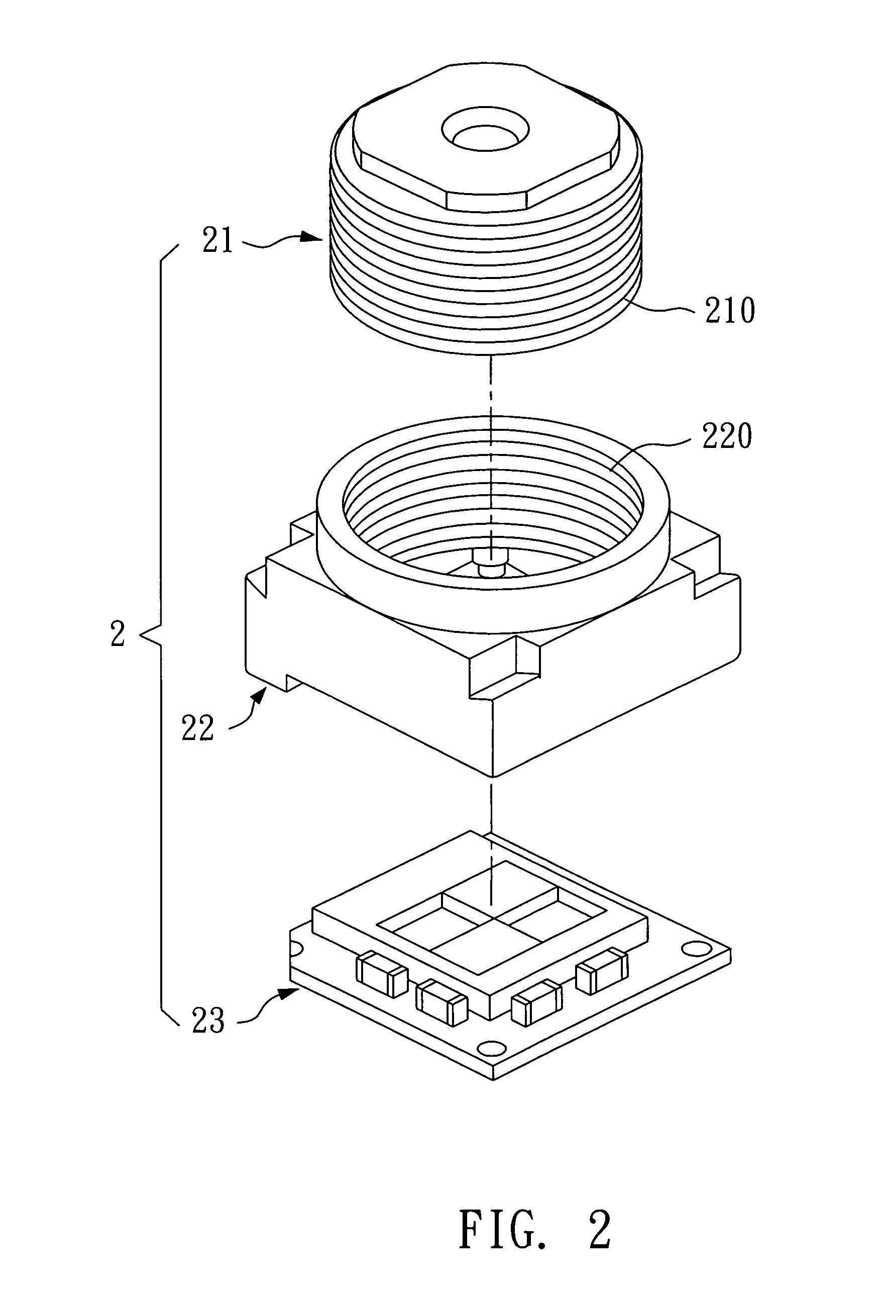
[0019] Please refer to FIG. 2, which shows an exploded view of a camera module 2 according to the present invention. The camera module 2 of this invention comprises a lens 21, a lens holder 22, and an image sensor board 23. The lens 21 and the lens holder 22 are engaged with each other. The image sensor board 23 is located under the lens holder 22 for the forming of an image. By adjusting the lens 21, the best focus of the camera module 2 can be reached.

[0020] In one exemplary embodiment, the engagement of the lens 21 and the holder 22 may be adapted by outer threads 210 of the lens 21 and inner threads 220 of the holder 22. Additionally, the engagement of the threads 210 and 220 can make the lens 21 movable; therefore, by moving the lens 21 to adjust the focus, the best focus of the camera module 2 can be reached.

[0021] The lens 21 o...


PUM


Abstract

This invention provides a camera module and a manufacturing process thereof. The camera module is compatible with surface mount technology (SMT) machines for bonding onto a main board. The camera module comprises a lens, a lens holder, and an image sensor device. The lens and the lens holder are connected to each other, and the image sensor device is located under the lens holder. The lens is formed from a heatproof material for enduring the high-temperature process of an SMT soldering machine. The lens holder is also formed from a heatproof material for enduring the high-temperatures process of the SMT soldering machine. The camera module can thus be a surface mount device (SMD) to be bonded by SMT machines onto the main board of a system.

Description

BACKGROUND OF THE INVENTION [0001] 1. Field of the Invention [0002] The present invention relates to a camera module, and more particularly, to a high heatproof camera module. [0003] 2. Description of the Related Art [0004] A wide variety of audio and video information is now widely available in digital formats. An important device for the inputting and outputting of such information is the camera module. Because of its applicability in a broad array of fields, from small devices such as mobile phones, personal digital assistants (PDAs) to large devices such as large digital video cameras (including monitor systems), the digital camera module is becoming more and more useful. [0005] Please refer to FIG. 1. When the traditional camera module 11 is assembled onto a main board 12 of a system, such as a mobile phone system, a laptop computer system, a digital camera system, or a digital video system, a socket 13 is usually required to connect the camera module 11 with the main board 12....

Claims


Application Information

Patent Timeline
Patent Type & Authority Applications(United States)
IPC IPC(8): H04N5/225G02B13/16H04N5/335H04N101/00
CPCH04N5/2253H04N5/2257H04N23/54H04N23/57
Inventor LUNG, CHIEN-LIH
Owner PREMIER IMAGE TECH
Why Eureka
Try Eureka